


Quick Research
Generate reliable direction feasibility study reports for your R&D in just a few steps.

Technical Q&A
Discover and master advanced knowledge NOW. Basics, ideas, possibilities, all at once.

Find Solutions
As an expert in R&D theories, this can generate solutions to your technical problems instantly.

Evaluate Feasibility
Analyze your overall solution with one click, know your potential R&D risks in advance.

Monitor Landscape
Get weekly tech updates, stay abreast of the latest tech innovations and key insights.
Method and system for machining slender molded contact pin of glasses leg
A processing method and technology of a processing system, applied in metal processing equipment, manufacturing tools, grinding workpiece supports, etc., can solve problems such as mirror polishing that cannot guarantee straightness and parallelism, bending and deformation of slender forming pins of temples, etc.
- Summary
- Abstract
- Description
- Claims
- Application Information
AI Technical Summary
Problems solved by technology
Method used
Image

Examples
Embodiment 1
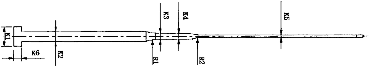
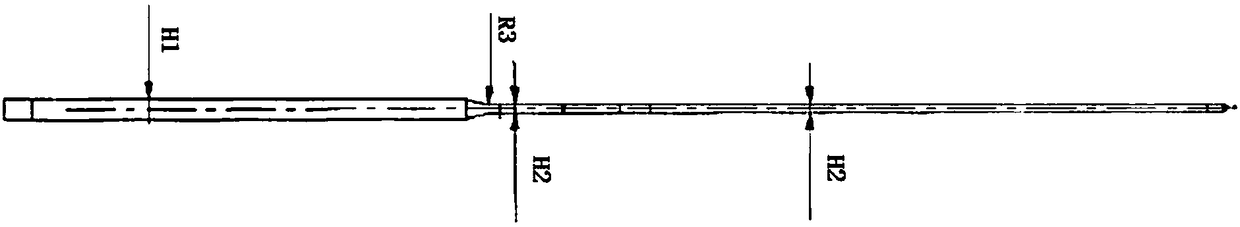
[0074] A method for processing slender and shaped pins for spectacle legs, comprising the following steps:
[0075] S1. The material is cut off after leaving the warehouse, quenched in a salt bath and straightened by heat, and the straightness is guaranteed to be within 0.02;
[0076] S2. The centerless grinder uniformly processes the upper and lower dimensions of the rod material, that is, 10.5mm to 10.6mm, within Ra0.2. The specific steps are:
[0077] The rod material is φ11mm round material, and the centerless grinder rounds the outer circle and controls the straightness within 0.04. Centerless grinding is divided into rough grinding and fine grinding: when rough grinding, the roughness of the grinding wheel can reach Ra2.5-3.6, which is easy To remove the curvature of the material, the rough machining of the product is divided into three times, and the measurement should be done slowly. The first round is enough, the second time is slowly lowered to grind away 0.03mm, the...
Embodiment 2
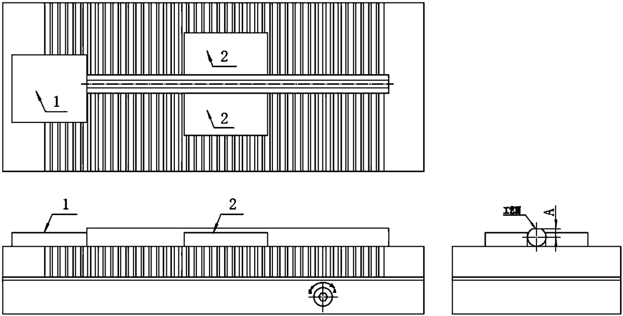
[0099] A processing system adopted in the method for processing the slender shape of the spectacle legs described in Embodiment 1, including a surface grinder system and a polishing system;
[0100] The surface grinder system includes a working magnetic table of the machine tool and a surface grinding mechanism for each part;
[0101] The flat grinding mechanism of each position includes:
[0102] The process surface flat grinding mechanism is composed of a rear stopper 1, a side stopper 2, and a grinding wheel. The rear stopper 1 withstands one end of the product, and the side stopper 2 clamps both sides of the product;
[0103] 3.0mm thick first side flat grinding mechanism, composed of rear stopper 23 and grinding wheel 2, rear stopper 23 withstands one end of the product;
[0104] The second surface flat grinding mechanism of the 3.0mm thickness part is composed of a rear stopper 34 and a grinding wheel 3, and the rear stopper 34 withstands one end of the product;
[010...
PUM
| Property | Measurement | Unit |
|---|---|---|
| Thickness | aaaaa | aaaaa |
| Thickness | aaaaa | aaaaa |
| Thickness | aaaaa | aaaaa |
Abstract
Description
Claims
Application Information
 - R&D Engineer
- R&D Manager
- IP Professional
- Industry Leading Data Capabilities
- Powerful AI technology
- Patent DNA Extraction
Browse by: Latest US Patents, China's latest patents, Technical Efficacy Thesaurus, Application Domain, Technology Topic, Popular Technical Reports.
© 2024 PatSnap. All rights reserved.Legal|Privacy policy|Modern Slavery Act Transparency Statement|Sitemap|About US| Contact US: help@patsnap.com