
Three-dimensional printing method based on DLP (digital light processing) projection photocuring and equipment

A technology of 3D printing and projection light, which is applied in metal processing equipment, 3D modeling, 3D object support structure, etc., can solve the problems of part forming speed increase, process cost increase, part fine feature distortion, etc., to ensure the forming dimensional accuracy and fineness, improve molding efficiency, and reduce data distortion

Pending Publication Date: 2018-08-21
NANTONG INST OF TECH
View PDF5 Cites 18 Cited by
  • Summary
  • Abstract
  • Description
  • Claims
  • Application Information

AI Technical Summary

Problems solved by technology

[0002] In the DLP projection light curing system, the digital chip used is usually a digital micromirror device (DMD), which has a fixed size. Only a fixed imaging format and feature resolution can be achieved through the imaging lens, which will result in an incompatibility between size and precision. For example, when using a small size for high-precision projection, it is possible to achieve a few microns in the size of the part, but this will limit the overall molding speed of the part; when using a larger size projection, it can be effectively The molding speed of the parts is guaranteed, but the fine features in the parts are seriously distorted, the imaging accuracy cannot be guaranteed, and the energy cannot be fully utilized
The methods for solving the above problems in the prior art mainly include the following two types: (1) splicing digital chip arrays, but this method is expensive, which increases the process cost, and at the same time cannot guarantee a very small splicing gap, and it is difficult to ensure the molding accuracy; (2) ) splicing imaging surface method, by dividing the imaging surface into regions and splicing exposure, but the efficiency is low

Method used


Image

  • Three-dimensional printing method based on DLP (digital light processing) projection photocuring and equipment
  • Three-dimensional printing method based on DLP (digital light processing) projection photocuring and equipment

Examples


Embodiment Construction

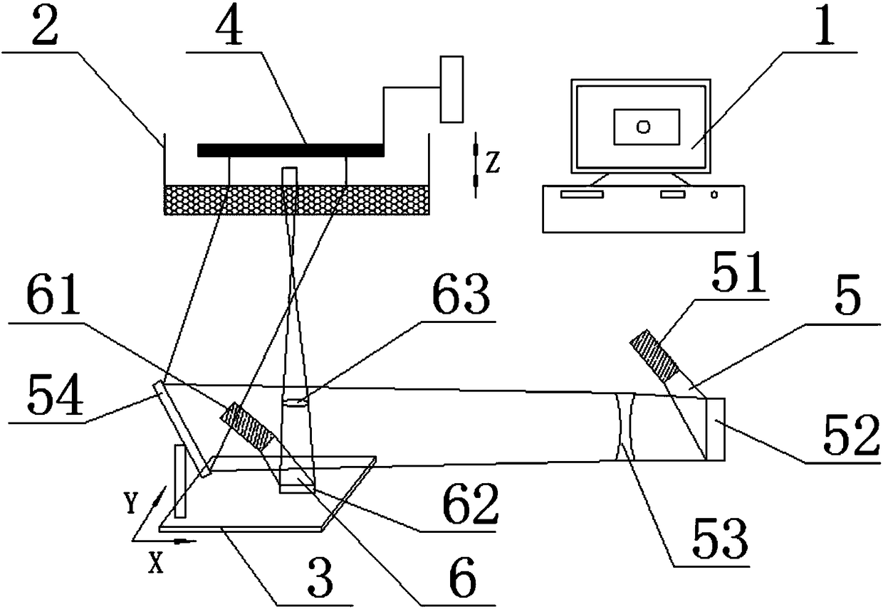
[0039] The core of the present invention is to provide a three-dimensional printing method and equipment based on DLP projection light curing. In order to enable those skilled in the art to better understand the technical solution of the present invention, the present invention will be further described in detail in conjunction with specific examples below.

[0040] refer to figure 1 , which shows the implementation flow chart of the DLP-based projection photocuring three-dimensional printing method of the present invention. First, use modeling units such as Proe or Solidworks to build a 3D model of the pre-generated object, and avoid sharp corners or narrow gap structures during the modeling process. The above-mentioned three-dimensional model is simulated and layered by using the digital slicing unit, and the thickness value of each layer must be set according to the actual working capacity of the printing device to produce multiple Z-direction (ie, height direction) cross-s...


PUM


Abstract

The invention discloses a three-dimensional printing method based on DLP (digital light processing) projection photocuring. The method particularly comprises the following steps of: constructing a three-dimensional model of an object in advance, directly obtaining a cross section of each slice to be printed, and performing processing, area division and normal value judgment through corresponding units. The data distortion is reduced; the forming precision of printing data of the method is improved; areas to be printed and printing equipment with different performance are reasonably adapted, sothat the forming dimension precision and fineness of the object are guaranteed; and the forming efficiency is improved. In addition, the invention further discloses printing equipment adapted to thethree-dimensional printing method based on the DLP projection photocuring.

Description

technical field [0001] The invention relates to the technical field of three-dimensional printing rapid prototyping, in particular to a method and equipment for three-dimensional printing based on DLP projection light curing. Background technique [0002] In the DLP projection light curing system, the digital chip used is usually a digital micromirror device (DMD), which has a fixed size. Only a fixed imaging format and feature resolution can be achieved through the imaging lens, which will result in an incompatibility between size and precision. For example, when using a small size for high-precision projection, it is possible to achieve a few microns in the size of the part, but this will limit the overall molding speed of the part; when using a larger size projection, it can be effectively The molding speed of the parts is guaranteed, but the fine features in the parts are seriously distorted, the imaging accuracy cannot be guaranteed, and the energy cannot be fully utili...

Claims


Application Information

Patent Timeline
IPC IPC(8): B29C64/124B29C64/386B29C64/393B33Y50/00B33Y50/02G06T17/00G06T7/13
CPCG06T7/13G06T17/00B29C64/124B29C64/386B29C64/393B33Y50/00B33Y50/02
Inventor 姜杰顾海李彬曹赛男张捷吴国庆杨建春黄天成
Owner NANTONG INST OF TECH
Learn More