
Differential common-mode inductor

A technology of common-mode inductors and winding slots, which is applied in the field of inductors, can solve the problems of poor high-frequency performance of inductors, system failures, and cumbersome processes, and achieve low manufacturing costs, high application value, and simple overall structure. Effect

Pending Publication Date: 2018-08-17
东莞市立宇电子有限公司
View PDF0 Cites 1 Cited by
  • Summary
  • Abstract
  • Description
  • Claims
  • Application Information

AI Technical Summary

Problems solved by technology

However, each component of the inductor has high-frequency non-ideal characteristics, especially as the frequency increases, due to the existence of parasitic parameters, the high-frequency performance of the inductor becomes worse. At this time, the ability of the inductor to eliminate common-mode interference and differential-mode interference is reduced, which may cause the whole system to not work properly
[0004] In the prior art, differential-mode inductors and common-mode inductors need to be used together. Most of them are differential-common-mode integrated filter inductors. The differential-mode and common-mode inductors are integrated together. One magnetic ring uses ferrite material with high magnetic permeability, and one magnetic The ring is made of low magnetic permeability iron powder core material, but this structure requires two kinds of magnetic cores, which are bulky and cumbersome.

Method used


Image

  • Differential common-mode inductor
  • Differential common-mode inductor
  • Differential common-mode inductor

Examples


Embodiment Construction

[0023] The present invention will be further described below in conjunction with the accompanying drawings.

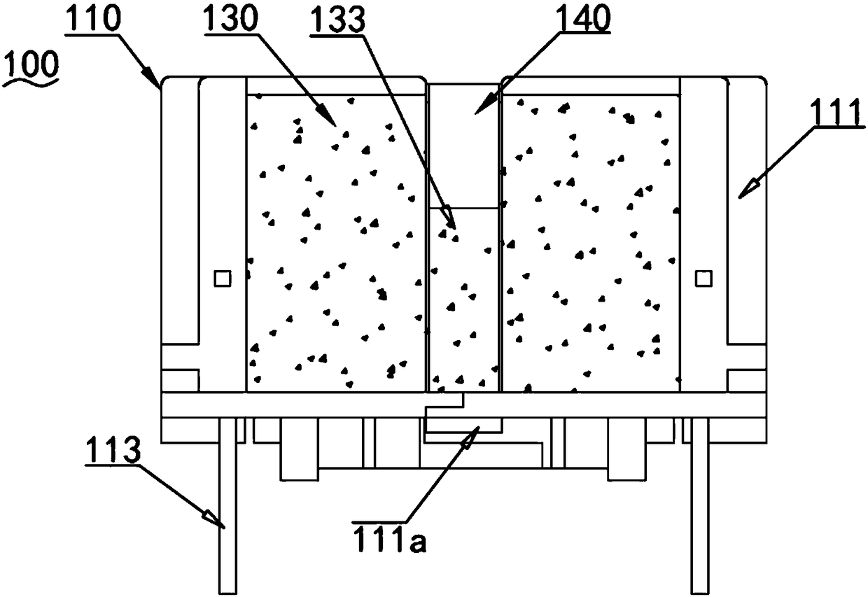
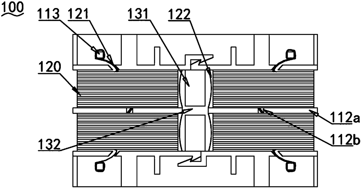
[0024] Such as Figure 1~2 Shown, are respectively the side view and the bottom view of the present invention.

[0025] A differential common mode inductor 100, comprising a framework 110 formed by fitting and fixing two card holders 111, the framework 110 is provided with several winding slots 112, and each winding slot 112 is provided with pins on one side 113, each winding slot 112 is wound with an enameled wire to form a coil 120, the coil 120 is extended with a connecting wire 121 and connected to the pin 113 by welding, the two sides of the skeleton 110 are correspondingly inserted with a magnetic core 130, located at The upper part of the magnetic core 130 is provided with a fixing clip 140 to fix and clamp the magnetic core 130 .

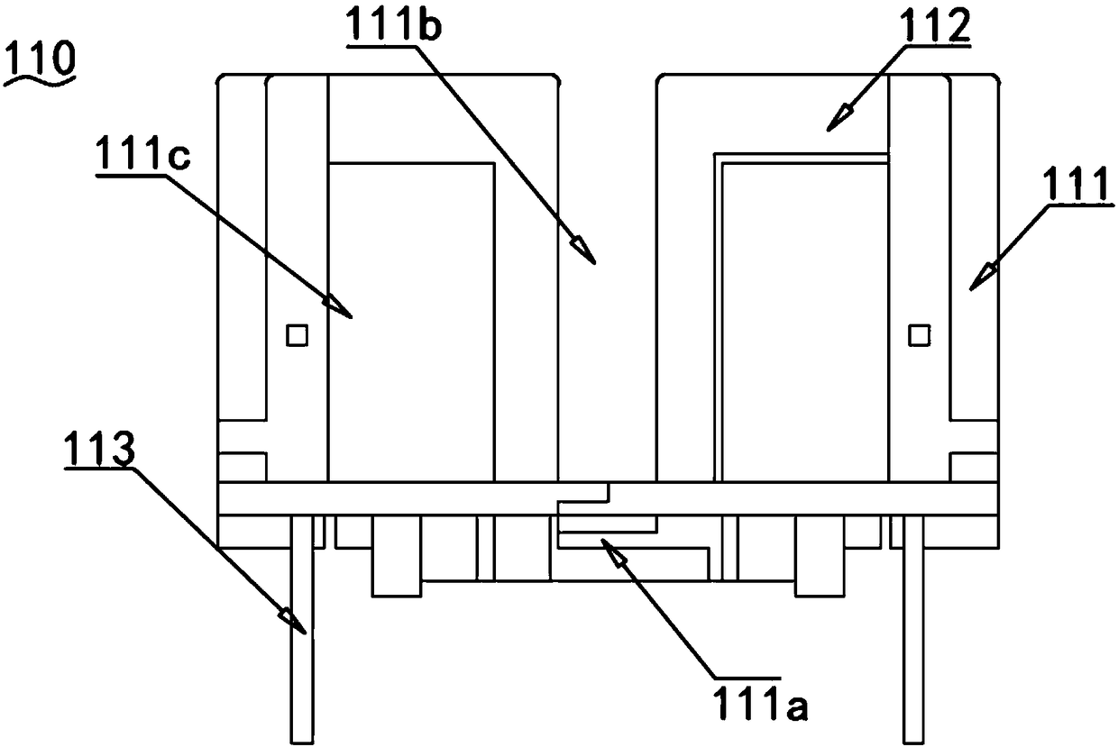
[0026] Such as image 3 As shown, the side of the two card holders 111 close to the pin 113 is correspondingly provided with a b...


PUM


Abstract

The invention relates to the technical field of an inductor, in particular to a differential common-mode inductor. The differential common-mode inductor comprises a framework, wherein the framework isformed by fixedly buckling two clamping seats, a plurality of winding grooves are formed in the framework, a pin is arranged at a side of each winding groove, an enameled wire is wound around each winding groove to form a coil, the coil is provided with a connection wire in an extension way, the connection wire is welded and connected with the pin, magnetic cores are correspondingly inserted intotwo sides of the framework, and fixed clamps are arranged at upper parts of the magnetic cores and are used for fixedly clamping the magnetic cores. On the basis of the differential common-mode inductor, the magnetic core structure is changed, the volume and the height of the inductor are reduced, the utilization ratio of a magnetic component is improved, and the integration of a power electronicsystem is improved.

Description

technical field [0001] The invention relates to the technical field of inductors, in particular to a differential common mode inductor. Background technique [0002] Inductors are essential components in aerospace, digital products, electronic switches, photovoltaic power generation and many other fields. How to effectively design the inductance parameters, increase the power density, and improve the electromagnetic interference (EMI) situation is not only related to the normal operation of the system, but also related to the optimization of the overall performance and the stable and reliable operation of the control part. [0003] Inductance is an important means to improve EMI performance. However, each component of the inductor has high-frequency non-ideal characteristics, especially as the frequency increases, due to the existence of parasitic parameters, the high-frequency performance of the inductor becomes worse. At this time, the ability of the inductor to eliminate...

Claims


Application Information

Patent Timeline
IPC IPC(8): H01F27/255H01F27/26H01F27/28H01F27/29H01F27/30H01F27/32H01F17/04
CPCH01F17/04H01F27/255H01F27/26H01F27/2828H01F27/29H01F27/306H01F27/324H01F2017/0093
Inventor 胡诗立周新华
Owner 东莞市立宇电子有限公司
Learn More