
Stress sensor and electronic device with same

a technology of stress sensor and electronic device, which is applied in the direction of force measurement, force measurement apparatus, instruments, etc., can solve the problems of increasing the overall weight and overall height affecting the minimization and light weightiness of the electronic device,

Inactive Publication Date: 2009-10-01
ELAN MICROELECTRONICS CORPORATION
View PDF10 Cites 0 Cited by
  • Summary
  • Abstract
  • Description
  • Claims
  • Application Information

AI Technical Summary

Benefits of technology

[0008]It is an object of the present invention to provide a stress sensor to be attached onto an electronic device without considerably increasing the overall height or volume of the electronic device.
[0009]Another object of the present invention provides an electronic device having a stress sensor with a reduced height or volume.

Problems solved by technology

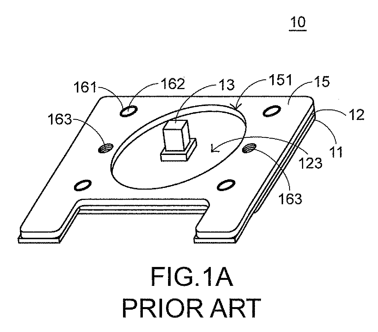
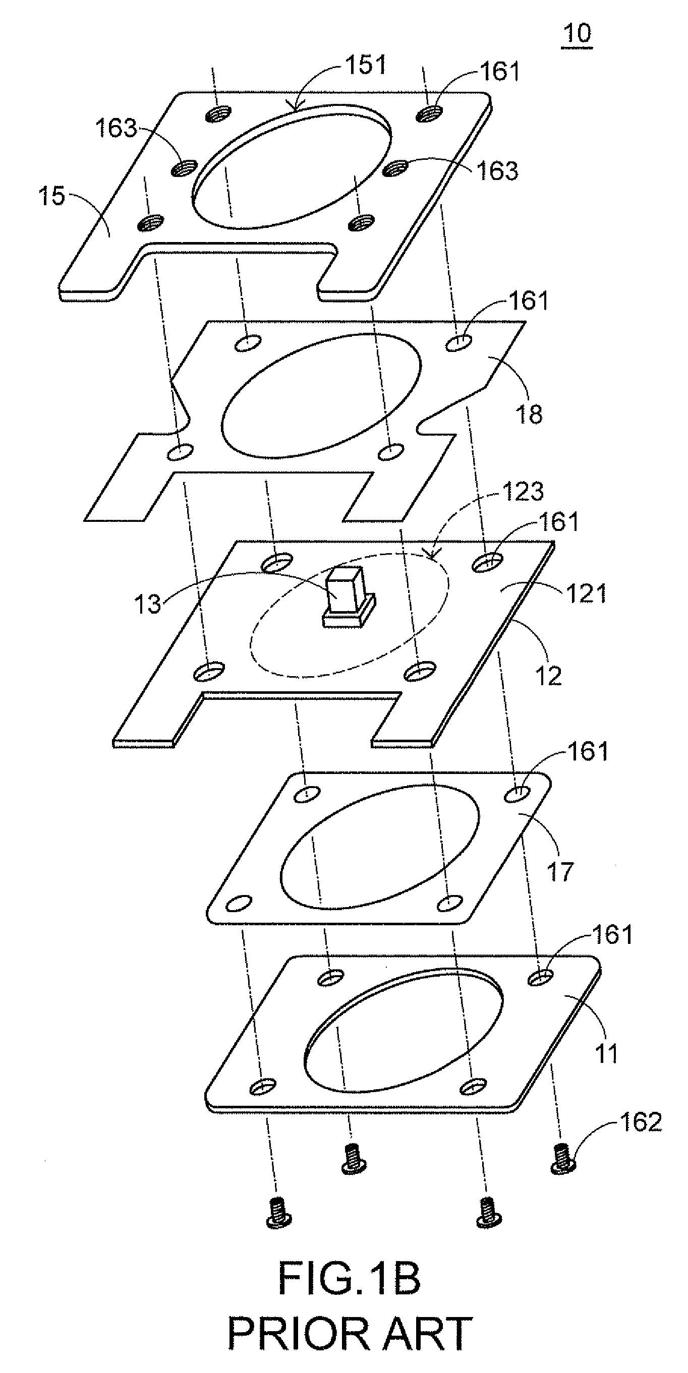
After the stress sensor 10 is mounted on the keyboard body 39, the overall height and the overall weight of the electronic device are increased and thus detrimental to minimization and light weightiness of the electronic device.

Method used


Image

  • Stress sensor and electronic device with same
  • Stress sensor and electronic device with same
  • Stress sensor and electronic device with same

Examples


Embodiment Construction

[0038]The present invention will now be described more specifically with reference to the following embodiments. It is to be noted that the following descriptions of preferred embodiments of this invention are presented herein for purpose of illustration and description only. It is not intended to be exhaustive or to be limited to the precise form disclosed.

[0039]In the following embodiments, the present is illustrated by referring to the configuration of a stress sensor and the connection between the stress sensor and a hardware input structure of an electronic device. Unless specifically stated, the operation principle of the stress sensor is substantially identical to that illustrated in the prior art and is not redundantly described herein.

[0040]FIGS. 4A and 4B are schematic side views illustrating a stress sensor to be respectively attached onto upper and lower surfaces of an assembled object / body of an electronic device according to a first preferred embodiment of the present ...


PUM


Abstract

The present invention relates to a stress sensor to be combined with an assembled object of an input unit of an electronic device. The stress sensor includes a circuit substrate and a pointing operation element disposed on a surface of the circuit substrate. The circuit substrate is combined with an assembled object of an input unit by a connecting mechanism such that the circuit substrate is directly attached onto a surface of the assembled object. As a result, the overall height of the stress sensor and the assembled object is reduced in comparison with the prior art.

Description

CROSS-REFERENCE TO RELATED APPLICATION[0001]This application claims priority under 35 U.S.C. §119 to Taiwan Patent Application No. 097110673, filed on Mar. 26, 2008, in the Taiwan Intellectual Property Office, the entire contents of which are hereby incorporated by reference.FIELD OF THE INVENTION[0002]The present invention relates to a sensor and an electronic device with such a sensor, and more particularly to a stress sensor and an electronic device with such a stress sensor.BACKGROUND OF THE INVENTION[0003]A pointing stick with pointing capability is widely used in many types of electronic devices such as notebook computers, mice, keyboards, hand-held devices, joysticks and the like. In this context, the pointing stick is also referred as a stress sensor. Generally, the stress sensor cooperates with a hardware input structure of an electronic device to implement the pointing function. For example, the common stress sensor of a notebook computer is arranged among keys near the mi...

Claims


Application Information

Patent Timeline
Patent Type & Authority Applications(United States)
IPC IPC(8): G01B7/16G06F3/0338G06F3/0354
CPCG01L5/223G01B7/18
Inventor SHIH-LANG, HUANG
Owner ELAN MICROELECTRONICS CORPORATION
Learn More