
Hydraulic driving device with moving cylinder body

A driving device and cylinder movement technology, applied in the direction of fluid pressure actuating device, etc., can solve the problems of low working efficiency, large space occupation, and bulky body, and achieve convenient operation, convenient transportation, and small size Effect

Inactive Publication Date: 2018-08-14
SUZHOU DOUSON DRILLING & PRODION EQUIP
View PDF7 Cites 2 Cited by
  • Summary
  • Abstract
  • Description
  • Claims
  • Application Information

AI Technical Summary

Problems solved by technology

[0003] In order to solve the above technical problems, the present invention provides a cylinder-moving hydraulic drive device, which adopts a structural model in which the hydraulic cylinder moves and the piston rod is fixed. The structure is simple, light in weight, small in size, and easy to move in deep sea , which can solve the problems of existing hydraulic drive devices such as large space occupation, bulky body, complex system, and low operating efficiency in deep sea

Method used


Image

  • Hydraulic driving device with moving cylinder body
  • Hydraulic driving device with moving cylinder body

Examples


Embodiment

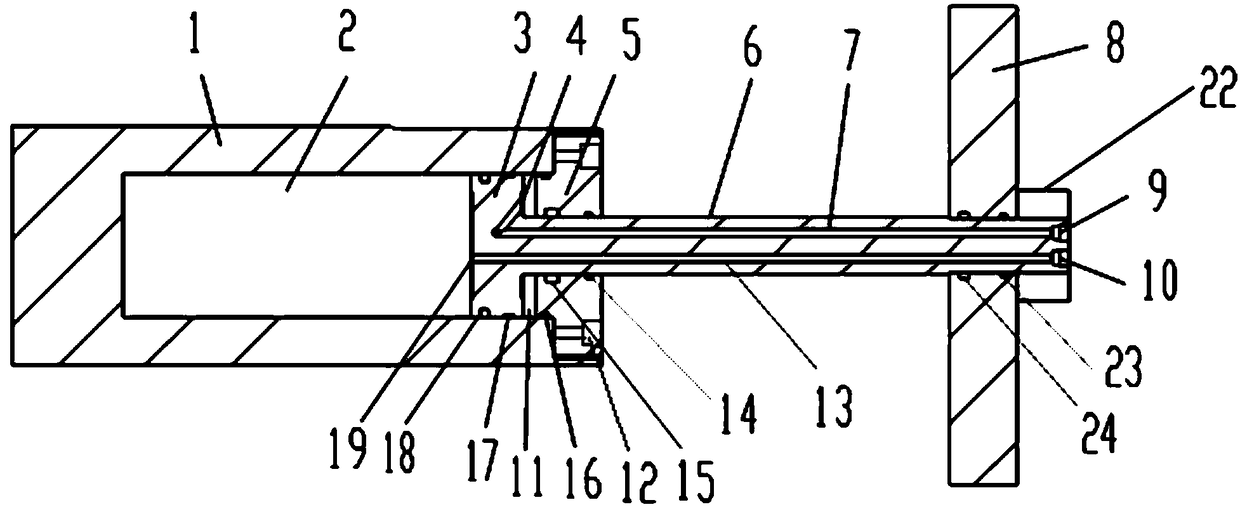
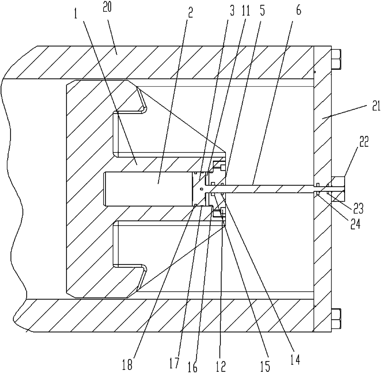
[0018] Such as figure 1 As shown, the present embodiment provides a cylinder-moving hydraulic drive device, which includes a fixed piston rod 6 and a reciprocating hydraulic cylinder 1; a hydraulic piston 3 is arranged inside the hydraulic cylinder 1, and the The right end of the piston rod 6 is fixed on the fixing member 8, and the left end extends into the interior of the hydraulic cylinder block 1 to connect with the hydraulic piston 3; the hydraulic piston 3 divides the interior of the hydraulic cylinder block 1 into the first oil injection chamber 11 on the right and The second oil injection chamber 2 on the left side; the piston rod 6 is provided with a flow guide mechanism for guiding the movement of hydraulic oil; the flow guide mechanism includes the first oil injection pipeline 7 and the second oil injection pipeline 13 arranged on the piston rod 6 The first oil injection pipeline 7 is provided with a first oil injection port 9 on the left end of the piston rod 6, an...


PUM


Abstract

The invention relates to a hydraulic driving device with a moving cylinder body. The hydraulic driving device with the moving cylinder body comprises a fixed piston rod and a reciprocating hydraulic cylinder body, wherein a hydraulic piston is arranged in the hydraulic cylinder body, the right end of the piston rod is fixed to a fixed part, the left end of the piston rod extends into the hydrauliccylinder body and is connected with the hydraulic piston, and the interior of the hydraulic cylinder body is divided into a right first oiling cavity and a left second oiling cavity by the hydraulicpiston. The hydraulic driving device with the moving cylinder body has the advantages of the simple structure, light weight and small size, and the structural pattern that the hydraulic cylinder bodymoves and the piston rod is fixed is adopted, so that the hydraulic driving device is convenient to move in deep seas, and the problems of large occupied space, heavy body, complex system, low operating efficiency in deep seas and the like of an existing hydraulic driving device can be solved.

Description

technical field [0001] The invention relates to the field of offshore oil and gas exploitation, in particular to a cylinder moving hydraulic drive device. Background technique [0002] The deep sea ram blowout preventer is the core well control equipment to ensure the safe and reliable exploitation of deep sea oil and gas, and the hydraulic drive device for opening and closing the well of the ram blowout preventer is also an indispensable device. At present, the commonly used hydraulic power drive devices for ram preventers use the structure of piston rod movement and the hydraulic cylinder body is fixed. The driving force is mainly generated by the movement of the piston rod to promote the movement of hydraulic oil, which usually requires The hydraulic cylinder and piston rod are separately configured to form a complete hydraulic device, which is large in size, heavy in shape, complex in transmission, high in failure rate, and inconvenient in transportation, especially in d...

Claims


Application Information

Patent Timeline
Patent Type & Authority Applications(China)
IPC IPC(8): F15B15/14F15B15/20
CPCF15B15/1457F15B15/1442F15B15/1447F15B15/1452F15B15/20
Inventor 刘冰舒志高尹恩来李树林庄会涛
Owner SUZHOU DOUSON DRILLING & PRODION EQUIP
Learn More