Sheet conveying mechanical hand with dedusting function and assemblies thereof

A technology of mechanical components and manipulators, applied in the direction of manipulators, chucks, manufacturing tools, etc., can solve the problem of dust affecting the suction of suction cups, etc., and achieve the best dust removal effect, reasonable structure, and reliable control.

Inactive Publication Date: 2018-08-14
CHANGSHU INSTITUTE OF TECHNOLOGY
View PDF9 Cites 6 Cited by
  • Summary
  • Abstract
  • Description
  • Claims
  • Application Information

AI Technical Summary

Problems solved by technology

[0004] The present invention is to solve the problem that the dust affects the suction force of the suction cup in the existing thin plate handling process, and provides a thin plate suction cup manipulator with dust removal function and its components

Method used


Image

  • Sheet conveying mechanical hand with dedusting function and assemblies thereof
  • Sheet conveying mechanical hand with dedusting function and assemblies thereof
  • Sheet conveying mechanical hand with dedusting function and assemblies thereof

Examples


Embodiment 1

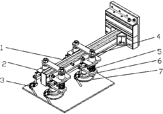
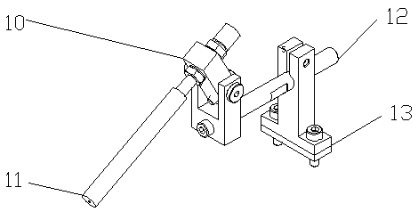
[0024] Such as figure 1 As shown, the present invention proposes a manipulator for thin plate transmission with dust removal function, including a dust removal device 3, an upper fixed plate 4, a middle fixed plate 2, a lower fixed plate 6, and a suction cup 7 through a suction cup connector 8. The suction cup 7 is fixed on the lower fixed plate 6 through the suction cup connector 8, the buffer device body is fixed between the upper fixed plate 4 and the middle fixed plate 2, and the lower end of the buffer device support rod passing through the spring is fixed on the lower fixed plate 6; the dust removal device 3 is fixed On the middle fixed plate 2, the limit body 9 is installed between the middle fixed plate 2 and the lower fixed plate 6, and the working distance between the lower fixed plate 6 and the middle fixed plate 2 is adjusted, and the dust removal device 3 is composed of the rotating device 10, The gas nozzle body 11, the long rod 12 and the fixed body 13 are compo...

Embodiment 2

[0026] A sucker-type manipulator assembly with dust removal function proposed by the present invention uses two manipulators, which are respectively arranged oppositely at the two ends of the guide rail, and the tops thereof are fixedly connected by an upper fixing plate, and there are more than two mechanical assemblies.

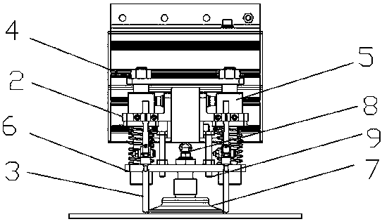
[0027] Such as figure 2 As shown, each suction cup manipulator includes a suction cup 7, a suction cup connector 8, a frame body 1, an upper fixing plate 4, a lower fixing plate 6, a buffer device 5, a limit body 9, a dust removal device 3, and a middle fixing plate 2. . Wherein the dedusting device is made up of rotating device 10 , gas nozzle body 11 , long rod 12 and fixed body 13 . The suction cup 7 and the suction cup connector 8 form a suction cup body, the suction cup body is fixed on the lower fixed plate 6, the buffer device 5 is multiple fixed by the upper fixed plate 4, the lower fixed plate 6 and the middle fixed plate 2, the limiter 9 and the...


PUM


Abstract

The invention discloses a sheet conveying suction cup type mechanical hand and assemblies thereof. The sheet conveying suction cup type mechanical hand comprises dedusting devices, upper fixing plates, middle fixing plates, lower fixing plates, suction cups, suction cup connectors and buffer devices; the suction cups are fixed to the lower fixing plates through the suction cup connectors; buffer device bodies are fixed between the upper fixing plates and the middle fixing plates, and the lower ends of buffer device supporting rods penetrating through springs are fixed to the lower fixing plates; and the dedusting devices are fixed to the middle fixing plates, limiting bodies are installed between the middle fixing plates and the lower fixing plates, and the operation distance between the lower fixing plates and the middle fixing plates is adjusted. The suction cup type mechanical hand has the advantages of being simple in structure, reliable in control, good in motion performance, convenient to use, capable of being used under the dust environment, and the like.

Description

technical field [0001] The invention relates to a pneumatic manipulator, in particular to a sheet conveying sucker-type manipulator and its components. Background technique [0002] In the machining and injection molding industry, many stations are for picking up objects. This kind of operation is generally simple in action and highly repeatable. At present, many picking machines or manipulators have been designed to meet this demand, including electric, hydraulic, and pneumatic, etc. The suction cup manipulator is one of the commonly used manipulators for thin plate handling, but for environments with more dust , The dust attached to the picked-up object will affect the adsorption force of the suction cup, which will have a great impact on production. Contents of the invention [0003] purpose of the invention. [0004] The present invention aims to solve the problem that dust affects the suction force of the sucker in the existing thin plate handling process, and prov...

Claims


Application Information

Patent Timeline
Patent Type & Authority Applications(China)
IPC IPC(8): B25J15/00B25J15/06
CPCB25J15/0019B25J15/0675
Inventor 郭兰中彭刘阳姚腾雷英庶李厅邓文飞
Owner CHANGSHU INSTITUTE OF TECHNOLOGY
Why Eureka
Try Eureka