Eureka AIR delivers breakthrough ideas for toughest innovation challenges, trusted by R&D personnel around the world.

Dedusting system for LED light bar and machine provided with dedusting system

A technology for LED light strips and dust removal systems, applied in cleaning methods and utensils, cleaning methods using gas flow, chemical instruments and methods, etc. Angle influence and other issues, to achieve the best dust removal effect

Inactive Publication Date: 2013-09-11
HONG FU JIN PRECISION IND (SHENZHEN) CO LTD +1
View PDF0 Cites 11 Cited by
  • Summary
  • Abstract
  • Description
  • Claims
  • Application Information

AI Technical Summary

Problems solved by technology

The LED light bar needs to go through the process of reflow soldering in the production process, but there may be impurities adsorbed on the LED light bar during the reflow process
Moreover, since the light-emitting surface of the LED is generally made of encapsulation resin, the encapsulation resin has a certain viscosity, so it is easy to absorb debris
The production process of traditional LED light strips generally does not take special measures against the problem of sundries in the reflow process, which will affect the appearance of LED light strips, the brightness and angle of light output

Method used


Image

  • Dedusting system for LED light bar and machine provided with dedusting system
  • Dedusting system for LED light bar and machine provided with dedusting system

Examples


Embodiment Construction

[0012] The present invention will be further described in detail below in conjunction with the accompanying drawings.

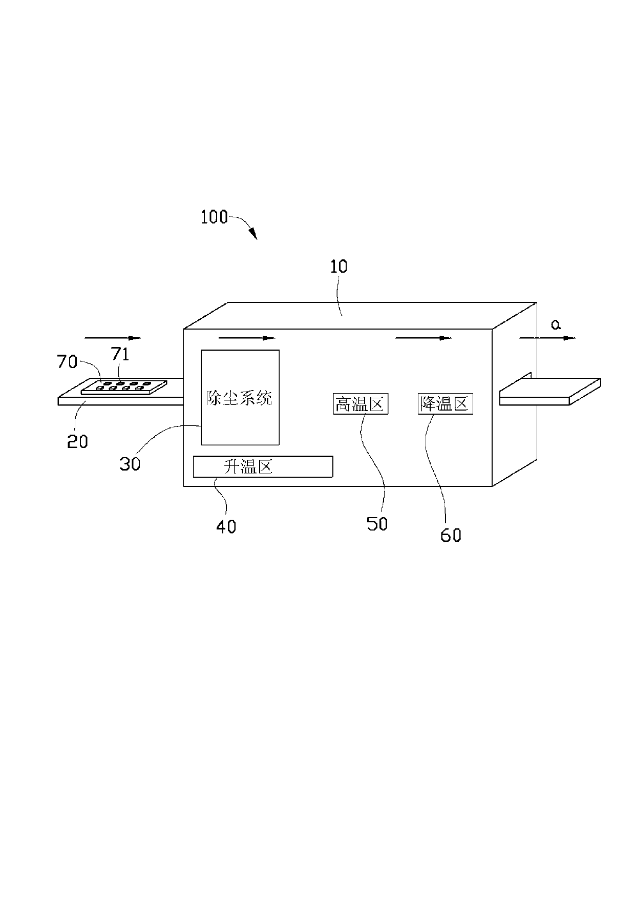
[0013] see figure 1 , shows a schematic diagram of a machine 100 with an LED light bar dust removal system according to the present invention. The machine 100 includes a working area 10 and a transport device. The transport device can pass through the working area 10 . In this embodiment, the transmission device is a transmission belt 20 . The working area 10 includes a dust removal system 30 , a heating zone 40 , a high temperature zone 50 and a cooling zone 60 . like figure 1 As shown, the conveyor belt 20 moves in the direction a. An LED light bar 70 with a plurality of LEDs 71 is mounted on the conveyor belt 20 and enters the working area 10 as the conveyor belt 20 moves. Entering the working area 10 from the conveyor belt 20 , passing through the heating zone 40 , the high temperature zone 50 and the cooling zone 60 successively, and then output fr...


PUM


Abstract

A dedusting system for an LED light bar comprises an airflow generation device. When the LED light bar passes by the dedusting system, the airflow generation device generates air flow to take away dust attached on the LED light bar. The machine provided with the dedusting system for the LED light bar comprises an operation area and a transmission device, wherein the transmission device passes by the operation area, the LED light bar is placed on the transmission device, the operation area comprises a heating area, a high-temperature area and a cooling area, and the dedusting system is located in the heating area. According to the dedusting system, the airflow generation device generates the air flow which can act on the dust attached onto the LED light bar and remove the dust. Therefore, the dedusting device provided by the invention can realize a better dedusting effect.

Description

technical field [0001] The invention relates to a dust removal system, in particular to an LED light bar dust removal system and a machine with the dust removal system. Background technique [0002] The LED (Light-Emitting Diode, light-emitting diode) industry is one of the most watched industries in recent years. So far, LED products have energy saving, power saving, high efficiency, fast response time, long life cycle time, and no Mercury, with its environmental benefits, has been used for lighting purposes. The LED light bar needs to go through the process of reflow soldering during the production process. However, during the reflow process, there may be impurities adsorbed on the LED light bar. Moreover, since the light-emitting surface of the LED is generally made of encapsulation resin, the encapsulation resin has a certain viscosity, so it is easy to absorb sundries. The production process of traditional LED light strips generally does not take special measures agai...

Claims


Application Information

Patent Timeline
Patent Type & Authority Applications(China)
IPC IPC(8): B08B5/02B08B5/04B08B13/00
Inventor 赖志成
Owner HONG FU JIN PRECISION IND (SHENZHEN) CO LTD
Why Eureka
Eureka Blog
Learn More