A Compensation Method for Motor Driving PWM Dead Zone

A compensation method and motor drive technology, applied in the field of motor compensation control and motor, can solve the problems of poor stability, low measurement accuracy, limited application of a single method, and achieve the effect of sufficient compensation and reduced requirements.

Active Publication Date: 2021-06-01
江西精骏电控技术有限公司
View PDF0 Cites 0 Cited by
  • Summary
  • Abstract
  • Description
  • Claims
  • Application Information

AI Technical Summary

Problems solved by technology

Existing dead zone compensation methods have disadvantages such as low measurement accuracy, poor stability, and limited application of a single method

Method used


Image

  • A Compensation Method for Motor Driving PWM Dead Zone
  • A Compensation Method for Motor Driving PWM Dead Zone

Examples


Embodiment Construction

[0019] Take a 30kW pure electric drive motor as an example:

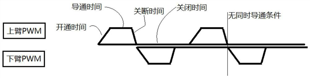
[0020] Step 1. Measure the turn-on and turn-off time of a transistor switch such as an IGBT under different voltages and currents, and use it as the basis of the dead time. The typical selection is 5 microseconds.

[0021] In step 1, when the IGBT is in the off state, the voltage is the power supply voltage, and the current is 0, and in the on state, the voltage is the conduction voltage drop, and the current is the load current. So step 1 is to test the time from turn-off to turn-on, and the time from turn-on to turn-off under different combinations of power supply voltage and load current. Just choose a meaningful combination of voltage and current (such as 300V 100A).

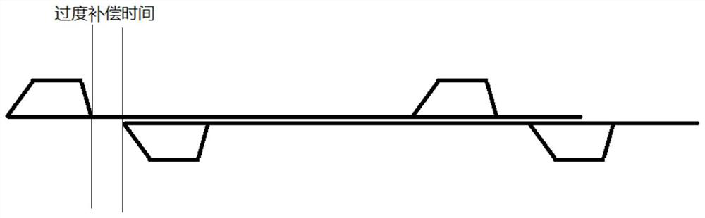
[0022] Step 2, measuring the change of the duty cycle of the PWM waveform under the conditions of different motor speeds, different output torques, and different voltages and currents.

[0023] The PWM waveform duty cycle in step 2 is a percenta...


PUM


Abstract

The invention discloses a method for compensating the dead zone of a motor driven PWM. Step 1. Measure the turn-on and turn-off time of a transistor switch such as an IGBT under different voltages and currents as the basis of the dead zone time. Step 2, measuring the change of the duty cycle of the PWM waveform under the conditions of different motor speeds, different output torques, and different voltages and currents. Step 3. According to the results of step 1 and step 2, set the maximum PWM duty ratio under different voltages and currents, so that the time when the upper and lower tubes are turned off at the same time is always greater than the sum of the time when the two switch tubes are turned off and on. Step 4. During the operation of the motor, conditions such as the rotational speed of the motor, the voltage and current of the DC bus, and the like are detected. It is judged that the duty ratio belongs to that situation, and compensation is made respectively. The invention measures the turn-on and turn-off time of the switch tube under different conditions, and sets the corresponding compensation strategy according to the dead duty ratio and its variation, so that the compensation is sufficient, and the requirements for test accuracy are reduced, and can be targeted Compensation is performed according to the running condition of the motor.

Description

technical field [0001] The invention relates to the field of motors, in particular to the field of motor compensation control. Background technique [0002] Electric vehicles, including pure electric vehicles, plug-in hybrid vehicles, and fuel cell vehicles, use inverter-driven electric motors to provide traction and, in some cases, braking. In the prior art, an electric drive system generally includes a DC power supply, a variable voltage converter VVT, an inverter, and a drive motor. [0003] The motor controller controls the operation of the inverter to achieve the purpose of controlling the acceleration and deceleration of the electric vehicle. The inverter consists of multiple transistor switch (such as IGBT insulated gate bipolar transistor) devices connected in a bridge configuration, and the motor controller turns on and off the switches to convert the DC voltage from the DC bus to an AC voltage delivered to the motor . [0004] When the motor controller drives th...

Claims


Application Information

Patent Timeline
Patent Type & Authority Patents(China)
IPC IPC(8): H02M1/38
CPCH02M1/38H02M1/385
Inventor 王长江王世强房伟
Owner 江西精骏电控技术有限公司
Why Eureka
Try Eureka