Layer-by-layer injection molding structure

A mold forming and injection molding technology, which is applied in the field of layer-by-layer injection mold forming structure, can solve problems such as cracks, low injection molding rate, air bubbles, etc., and achieve the effect of improving the success rate and fully compensating

Active Publication Date: 2021-01-15
深圳市美德精密科技有限公司
View PDF3 Cites 0 Cited by
  • Summary
  • Abstract
  • Description
  • Claims
  • Application Information

AI Technical Summary

Problems solved by technology

However, during the solidification process of raw materials, since the material may shrink, an open shrinkage compensation port is often left on the upper part of the mold, but the traditional shrinkage compensation port is small, and the wall surface of the product is often far away from the compensation position, making Openings and cracks are formed on the side wall of the workpiece blank, resulting in the scrapping of the product, especially for some thin-walled blanks, whose injection molding rate is low
Moreover, if the side wall of the product is too thin or too long during injection molding, the injection molding raw materials often cannot reach the molding position well, and air bubbles or cracks are likely to occur when the workpiece is molded.
In addition, when traditional injection molds are processed, each size of workpiece corresponds to a different mold, which makes the production cost higher, and when producing workpieces of different sizes, different molds need to be replaced, resulting in lower production efficiency

Method used


Image

  • Layer-by-layer injection molding structure
  • Layer-by-layer injection molding structure
  • Layer-by-layer injection molding structure

Examples


Embodiment Construction

[0014] Below in conjunction with embodiment the present invention is further described:

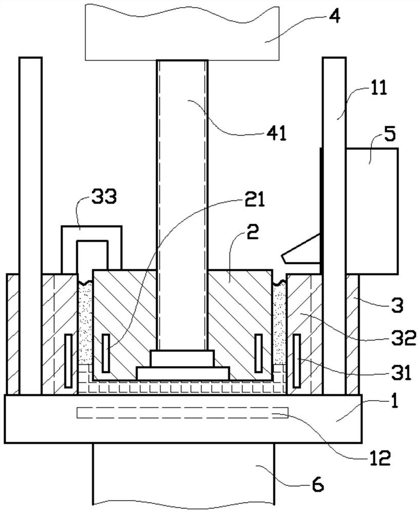
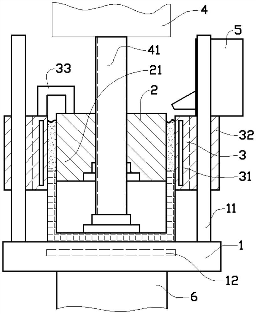
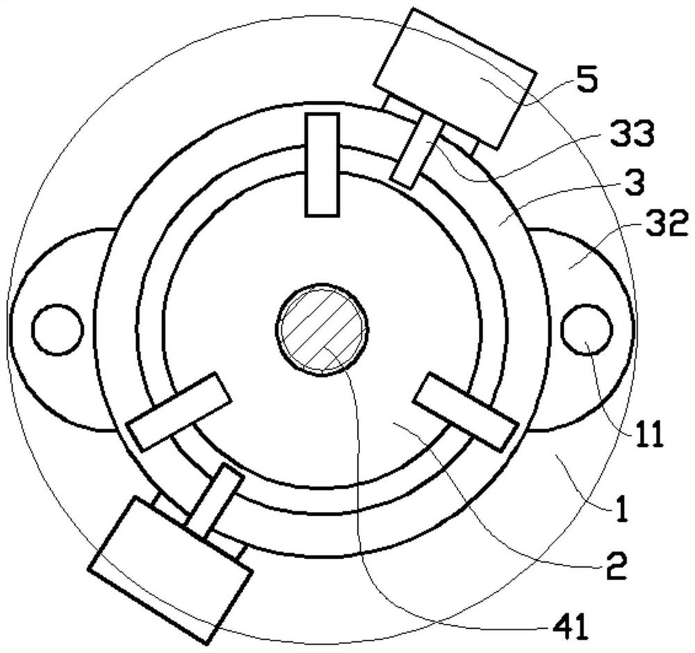
[0015] like figure 1 , figure 2 and image 3 As shown in the embodiment, this layer-by-layer injection mold molding structure includes an injection molding table 1 with an upper plane level, and the upper part of the injection molding table 1 is equipped with a lifting block 2 and a lifting ring 3, and the lifting ring 3 is wrapped in the lifting ring 3. Outside the block 2, there is a gap between the inner wall of the lifting ring 3 and the outer wall of the lifting block 2 to form an injection molding cavity. The lifting block 2 and the lifting ring 3 are fixedly connected through the upper part, and the upper part of the lifting block 2 is assembled There is a transmission module 4, the bottom of the transmission module 4 is equipped with a screw rod 41 that can rotate vertically from the axis, and a vertical screw hole is installed in the middle of the lifting block 2, and the scre...


PUM


Abstract

The invention provides a layer-by-layer injection molding type mold forming structure. The layer-by-layer injection molding type mold forming structure comprises an injection molding platform with a horizontal upper plane. A lifting block and a lifting ring are assembled to the upper portion of the injection molding platform. The lifting ring is wrapped outside the lifting block to form an injection molding cavity. A vertical screw rod capable of rotating around the axis of the screw rod is assembled the lower portion of a transmission module. A vertical screw hole is formed in the middle of the lifting block. The screw hole and the screw rod are assembled in a screw driving mode. Fixed rods are slidably assembled to the outer portion of the lifting ring. The lifting block and the liftingring move up and down along with rotation of the screw rod. The lower portion of the lifting block and the lower portion of the lifting ring are level. The lower portion of the lifting block is higherthan that of the lifting ring. An injection molding module is fixedly connected to the lifting ring. Element products with different heights can be obtained through the injection molding structure. Meanwhile, during injection molding, the compensation distance of the injection molding structure is short. Thus, compensation is sufficient, and the injection molding success rate is increased.

Description

technical field [0001] The invention belongs to the technical field of injection molding equipment, and in particular relates to a layer-by-layer injection molding mold forming structure. Background technique [0002] Injection molding is a molding method for industrial products. In the injection molding process, the mold that needs to be poured or die-casted is usually assembled first, and then the molten material is placed in the injection cavity for injection molding. After the material is formed, the mold is opened to obtain the required product blank, and then further processing is carried out according to the size of the product. The rough obtained by injection molding is closer to the shape of the product, the cutting waste is greatly reduced during processing, the processing efficiency is higher, and the processing cost is lower. The traditional injection molding method is to shape the injection cavity first, then fill the injection cavity with molten raw materials...

Claims


Application Information

Patent Timeline
Patent Type & Authority Patents(China)
IPC IPC(8): B29C45/03B29C45/17B29C45/26
CPCB29C45/03B29C45/17B29C45/2602
Inventor 陈思霖
Owner 深圳市美德精密科技有限公司
Why Eureka
Try Eureka