Regulated pump

A technology of pressure regulation and pump casing, which is applied in the field of oil pumps of internal combustion engines, can solve problems such as energy consumption and emissions, and achieve the effects of reducing pulsation and improving control characteristics

Inactive Publication Date: 2005-09-07
GKN SINTER METALS GMBH & CO KG
View PDF1 Cites 0 Cited by
  • Summary
  • Abstract
  • Description
  • Claims
  • Application Information

AI Technical Summary

Problems solved by technology

The resulting excess oil supply is exhausted energy-intensively via an overpressure limiting valve

Method used


Image

  • Regulated pump
  • Regulated pump
  • Regulated pump

Examples


Embodiment Construction

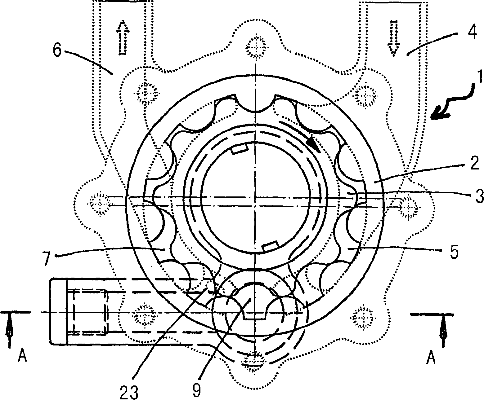
[0039] figure 1 A top view is shown of a pump 1 , in particular an oil pump for an internal combustion engine, which is equipped with a rotor arrangement designed as a cycloidal rotor, which comprises an outer rotor 2 and an inner rotor 3 . The pump 1 has an inlet 4 to a suction area 5 and an outlet 6 to a pressure area 7 . Both areas are designed to be kidney-shaped.

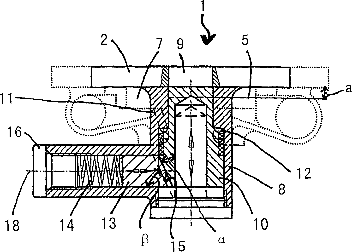
[0040] figure 2 represents the pump 1 according to the present invention along figure 1 A section of the line A-A in the center. A suction zone 5 and a pressure zone 7 are arranged on the pump housing 8 . The suction area 5 and the pressure area 7 are sealably separated from each other by an axially displaceable control piston 10 delimiting a delivery chamber 9 . The pressure zone 7 has a pressure regulating channel 11 which is connected to a collar 12 of the control piston 10 . The control piston 10 cooperates at its end facing away from the delivery chamber 9 with a spring pin 13 arranged at right angl...


PUM


Abstract

The invention relates to a pump, in particular to oil pumps for internal combustion engines comprising a gear assembly or rotor assembly with one each of a pressure and suction region arranged in a pump housing, which may be sealed from each other by means of an axially displaceable piston valve which defines a supply chamber and a housing cover, closing the pump housing. The pressure region comprises a pressure channel connected to the waist of the control piston, whereby the control piston cooperates with a plunger on the end thereof facing the supply chamber, which is arranged at right angles to the control piston. The plunger is pre-tensioned against the control piston by means of a pressure spring, and the plunger and control piston are connected by means of a sliding surface, arranged at an angle to the control piston axis.

Description

technical field [0001] The invention relates to a pump, in particular an oil pump for an internal combustion engine, which is provided with a ring gear arrangement or a rotor arrangement, each with a pressure zone and a suction zone arranged in a pump housing, the two zones being delimited by a The axially displaceable control pistons of a delivery chamber are separable from one another and are provided with a housing cover which closes off the pump housing, wherein the pressure area has a pressure channel which is connected to the collar of the control piston. Background technique [0002] Improved forms of vehicles with low fuel consumption require optimization of both vehicle components and engine components. For the energy consumption of motor vehicles in frequent short-distance traffic and urban traffic, losses which are often determined by the actuation of auxiliary devices are of particular importance. The drive power of certain oil pumps that ensure engine lubricati...

Claims


Application Information

Patent Timeline
Patent Type & Authority Patents(China)
IPC IPC(8): F04C2/10F04C14/00F04C14/18F04C14/24F04C14/26F04C15/00F04C15/06F16N13/20
CPCF04C14/265F16N13/20
Inventor J·巴奇曼恩
Owner GKN SINTER METALS GMBH & CO KG
Why Eureka
Try Eureka