
Brushless direct current motor rotor

A brushed DC motor and rotor technology, which is applied in the direction of electrical components, electromechanical devices, magnetic circuit rotating parts, etc., can solve the problems of large harmonics of induced electromotive force, large noise and pulsation, waste of materials, etc., and achieve low noise and pulsation, Reduced loss and high efficiency

Inactive Publication Date: 2011-04-27
WENZHOU ACHR ELECTRIC MACHINERY
View PDF10 Cites 12 Cited by
  • Summary
  • Abstract
  • Description
  • Claims
  • Application Information

AI Technical Summary

Problems solved by technology

However, a uniform air gap is formed between the rotor and the stator of the above two technical solutions, and the main pole waveform of the magnetic field is a rectangular wave distribution, which has the disadvantages of large induced electromotive force harmonics, large noise and pulsation, and low efficiency; in addition, the permanent magnet is Concentric arc tile-shaped body, there is a disadvantage of material waste during cutting and processing

Method used


Image

  • Brushless direct current motor rotor
  • Brushless direct current motor rotor
  • Brushless direct current motor rotor

Examples


Embodiment Construction

[0014] The present invention will be further described below in conjunction with accompanying drawing and embodiment:

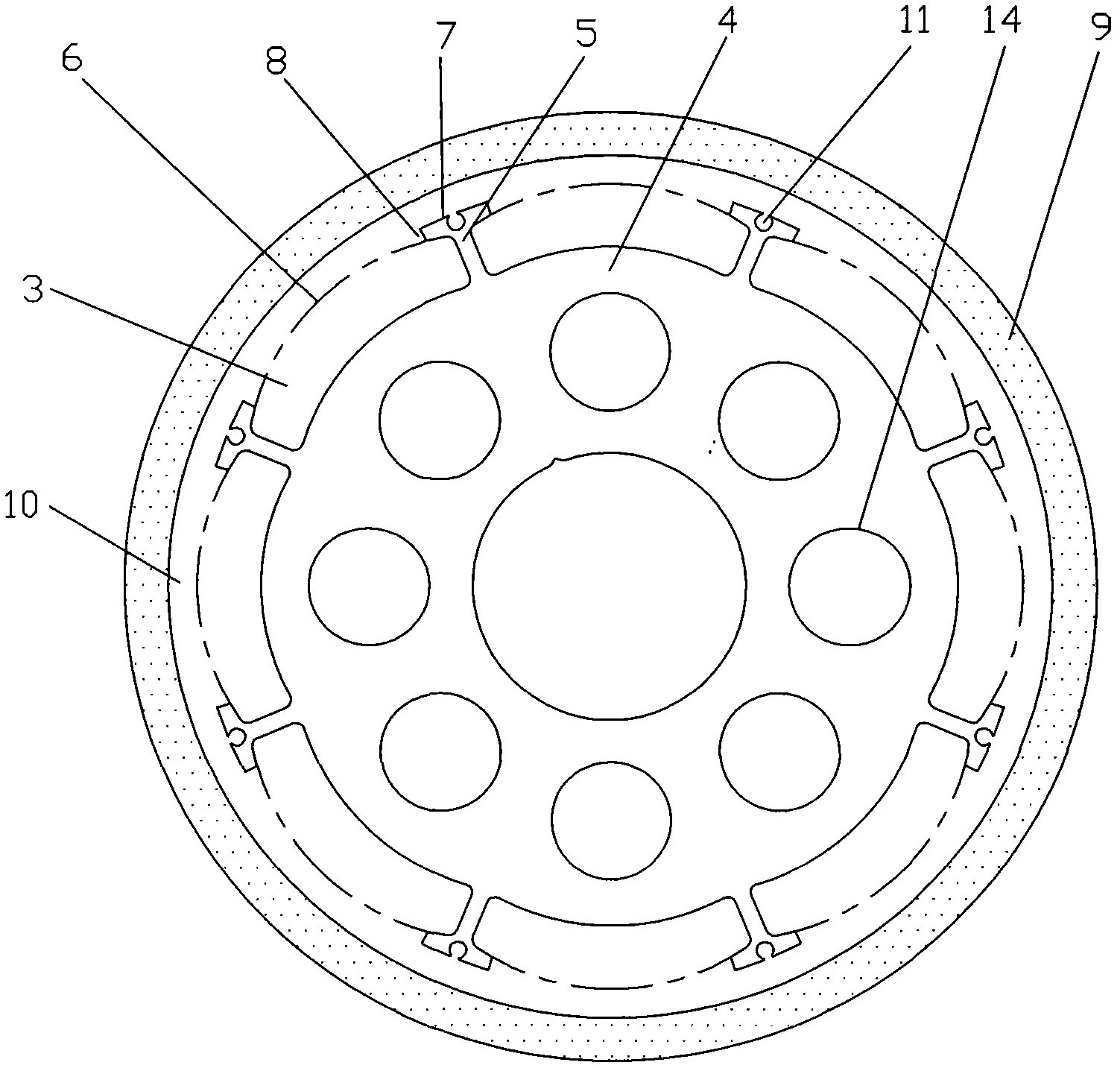
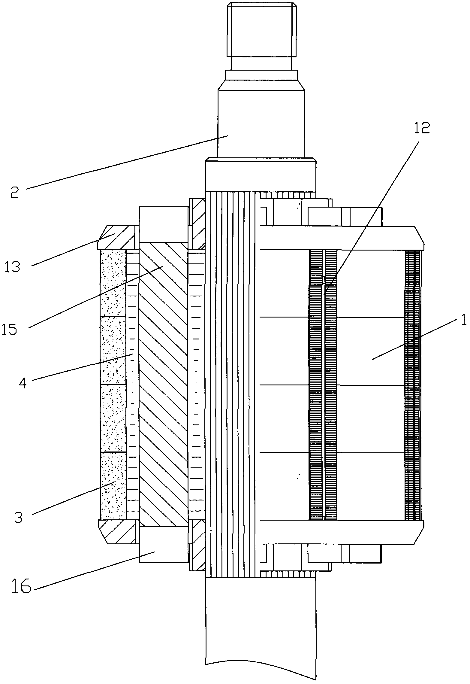
[0015] Such as figure 1 with 2 As shown, a brushless DC motor rotor includes a rotor core 1, a rotating shaft 2 and a permanent magnet 3. The rotor core 1 is composed of punched sheets 4 and connected into one body. The rotating shaft 2 is fixedly connected to the rotor core 1. The rotor An even number of T-shaped wedges 5 are evenly distributed on the outer surface of the iron core 1, and slots are formed between adjacent T-shaped wedges 5, and the permanent magnets 3 are correspondingly embedded in the slots, the permanent magnets 3 are thick in the middle, and the two ends Slightly thinner double-arc tile-shaped body, the middle part 6 of the permanent magnet 3 and the outer circle part 7 of the T-shaped wedge 5 are located on the rotation circumference of the rotor core 1, the middle part 6 of the permanent magnet 3 and the adjacent T A lower recess 8 i...


PUM


Abstract

The invention discloses a brushless direct current motor rotor, which comprises a rotor core, a revolving shaft and a permanent magnet, wherein the rotor core is formed by laminating and integrally connecting punched sheets; the revolving shaft is fixedly connected with the rotor core; even T-shaped wedges are uniformly distributed on the outer surface of the rotor core; a slot is formed between adjacent T-shaped wedges; the permanent magnet is correspondingly embedded into the slot and is a double-arc-shaped corrugated body of which the middle is thick and the two ends are thin; the middle part of the permanent magnet and the outer circle part of each T-shaped wedge are positioned on the rotation circumference of the rotor core; and a downward-concave part is formed between the middle part of the permanent magnet and an adjacent T-shaped wedge, so that non-uniform air gaps are formed between the rotor and a stator. The invention has the advantages that: main pole waveforms of a magnetic field are distributed in the form of sine waves; and the motor rotor has the advantages of small induced electromotive force harmonic wave, low noise, small pulsation and high efficiency.

Description

technical field [0001] The invention relates to a brushless direct current motor, in particular to a brushless direct current motor rotor. Background technique [0002] At present, brushless DC motors have been widely used in various occasions, and are also one of the key components of electric vehicles. The rotor structure and manufacturing process of brushless DC motors are also different. The more common one is the permanent magnet embedded structure, which is different from this The existing technology that is relatively close to the invention has the patent number ZL200920116549.1, and the utility model patent named "Brushless DC Motor Rotor", which discloses the following technical solutions: including rotor core, shaft and permanent magnet, rotor core It is composed of superimposed punches and connected into one body, and the rotating shaft is fixedly connected with the rotor core. The invention point is that an even number of T-shaped wedges are evenly distributed on...

Claims


Application Information

Patent Timeline
Patent Type & Authority Applications(China)
IPC IPC(8): H02K29/03H02K1/27
Inventor 薛肇江王华生
Owner WENZHOU ACHR ELECTRIC MACHINERY
Learn More