Pressure gauge and pressure monitoring system

A pressure gauge and pressure mode technology, which is used in the measurement of fluid pressure, measuring devices, instruments, etc., can solve the problems of data reliability, low intelligence of pressure gauges, and inability to detect real-time pressure gauge data.

Pending Publication Date: 2018-08-07
GUANGDONG POWER GRID CO LTD +1
View PDF5 Cites 4 Cited by
  • Summary
  • Abstract
  • Description
  • Claims
  • Application Information

AI Technical Summary

Problems solved by technology

[0004] Therefore, the existing pressure gauges have a low degree of intelligence, it is difficult to determine the pressure state intuitively, th...

Method used


Image

  • Pressure gauge and pressure monitoring system
  • Pressure gauge and pressure monitoring system
  • Pressure gauge and pressure monitoring system

Examples


Embodiment 1

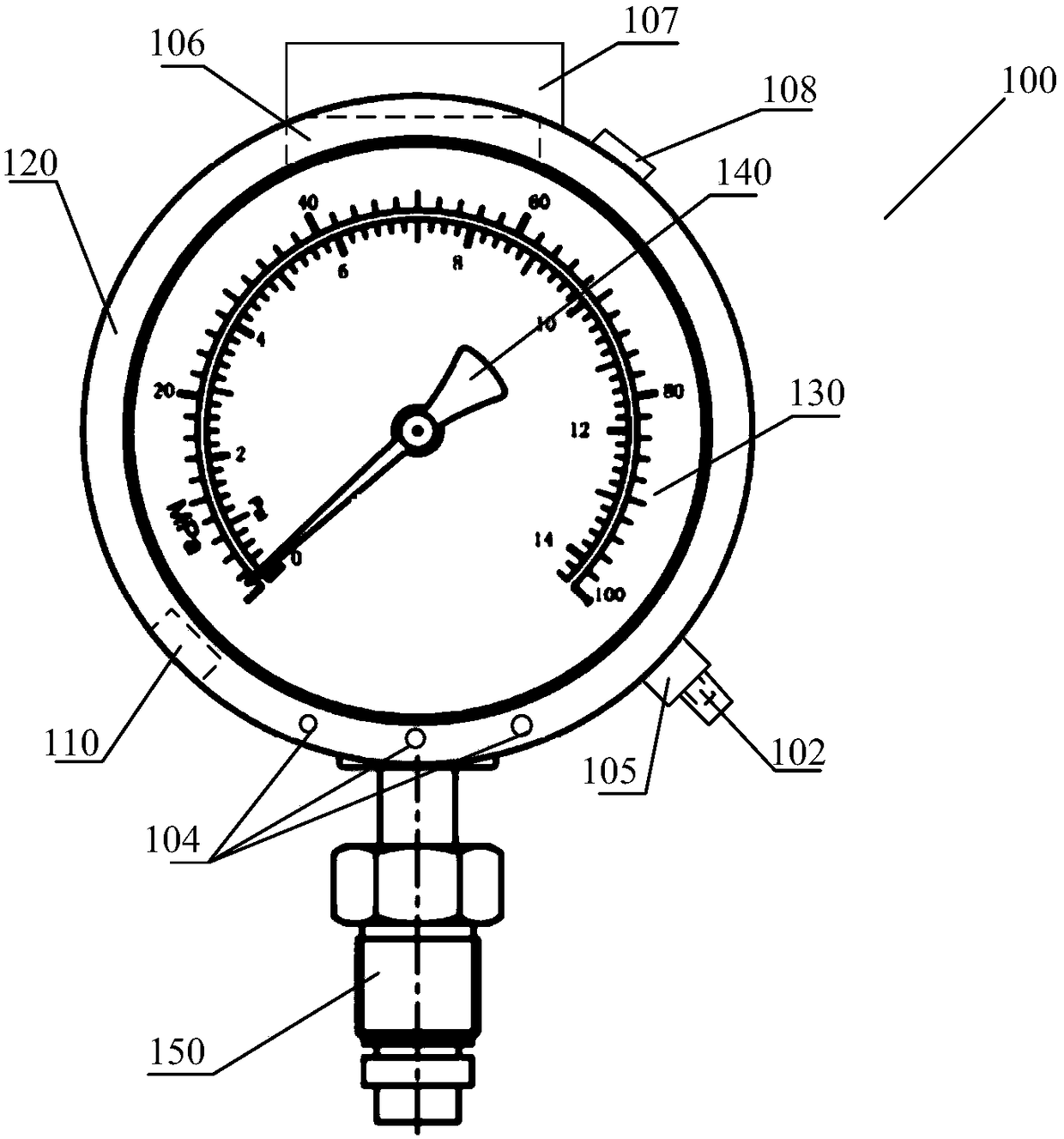
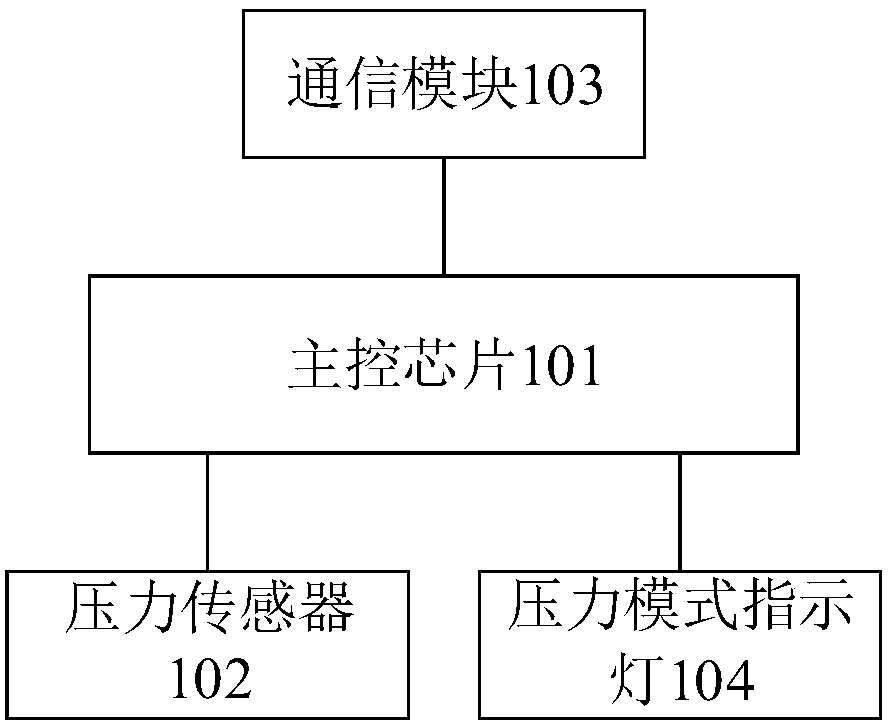
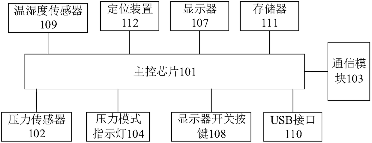
[0034] See figure 1 with figure 2 The pressure gauge 100 provided in this embodiment includes a pressure gauge body, which includes a pressure gauge housing 120, a dial 130, a pointer 140, a pressure connector 150, and a glass panel (not shown in the figure) covering the dial. A main control chip 101, a pressure sensor 102, and a communication module 103 are arranged in the pressure gauge housing 120, and a plurality of pressure mode indicator lights 104 are arranged on the surface of the pressure gauge housing. The pressure sensor, the communication module, and the pressure mode indicator are respectively connected to the main control chip; the main control chip is connected to the background monitor through the communication module, and the pressure connector 150 is connected to the SF6 gas.

[0035] In a possible embodiment, the pressure gauge body is a spring tube pressure gauge, and the pressure gauge housing is made of stainless steel. The glass panel can be made of toughe...

Embodiment 2

[0049] Figure 4 Shows a schematic structural diagram of a pressure monitoring system provided by an embodiment of the present invention, such as Figure 4 As shown, the pressure monitoring system includes a background monitoring machine 200 and a pressure gauge 100 as in the first embodiment; the pressure gauge is in communication connection with the background monitoring machine.

[0050] Specifically, the background monitoring machine obtains the pressure value through the communication module, analyzes the change trend of the pressure value, and predicts the change of the pressure value in advance, and does a good job of tracking and processing equipment leakage defects in time. Specifically, the pressure value at the current moment is extracted every preset time length, and when the pressure value reaches the preset number, the average difference of the pressure values ​​is calculated, and the pressure value is determined according to the average difference, the preset durat...


PUM


Abstract

The invention provides a pressure gauge and a pressure monitoring system. The pressure gauge comprises a pressure gauge body, wherein the pressure gauge body comprises a pressure gauge shell, a main control chip, a pressure sensor, a plurality of pressure mode indicator lamps and a communication module are arranged in the pressure gauge shell, and the surface of the pressure gauge shell is provided with a the plurality of pressure mode indicator lamps; the main control chip is connected with a background monitor by virtue of the communication module; the pressure gauge shell is provided with apressure interface, the pressure interface is communicated with SF6 gas, and the pressure sensor is arranged on the pressure interface; and the main control chip receives a pressure signal transmitted by the pressure sensor, the current pressure mode is determined, and the corresponding pressure mode indicator lamp is turned on according to the pressure signal and the pre-classified different pressure modes. The current pressure state can be intuitively and timely determined, a pressure value is read in real time, the manual transcription is not needed, and the influence of the personal subjective factor for on the data reliability is avoided.

Description

Technical field [0001] The invention relates to the technical field of electrical equipment control, in particular to a pressure gauge and a pressure monitoring system. Background technique [0002] At present, a large number of substations are equipped with electrical equipment using SF6 (sulfur hexafluoride) as the insulating medium, such as GIS (Gas Insulated Substation) equipment, circuit breakers, current transformers, etc., all of which are equipped with SF6 Pressure gauge. Insulation performance, arc extinguishing ability, airtightness and SF6 gas content are several criteria for judging whether high-voltage products are qualified, and the SF6 gas content directly affects the arc extinguishing ability and insulation performance of the equipment, so the SF6 gas content is monitored It is necessary. [0003] In the case of equipment leakage defects, operators need to regularly check the SF6 pressure value according to the leakage speed to prevent the deterioration of equipme...

Claims


Application Information

Patent Timeline
IPC IPC(8): G01L19/16G01L19/08G01L19/12G01L19/10G01L19/00
CPCG01L19/00G01L19/0092G01L19/083G01L19/086G01L19/10G01L19/12G01L19/16G01L2019/0053
Inventor 叶灿伦吴汝豪谢进英吴俊黄杰明黄国尊李绍良蒋绿海范建任燕周朝楠叶树伟黄铮陈锦洪徐光雄
Owner GUANGDONG POWER GRID CO LTD
Why Eureka
Try Eureka