Self-condensing reservoir

A water storage tank and self-condensing technology, applied in the configuration of water supply tanks, water supply devices, drinking water devices, etc., can solve the problems of inconvenient water supply and waiting for rescue, etc., and achieve convenient installation, good use prospects and promotion prospects, The effect of high coagulation rate

Inactive Publication Date: 2018-08-07
广西芸耕科技有限公司
View PDF0 Cites 1 Cited by
  • Summary
  • Abstract
  • Description
  • Claims
  • Application Information

AI Technical Summary

Problems solved by technology

[0002] Existing reservoirs generally add water to the reservoir by pumping water. If the water pump is broken or the water pipe bursts, it will cause inconvenient water supply, and the water can only be used after the problem is solved; this situation is very important for remote areas. It is especially serious in areas that are short of water or lack of water. If such a situation occurs, we can only wait for rescue.

Method used


Image

  • Self-condensing reservoir
  • Self-condensing reservoir

Examples


Embodiment 1

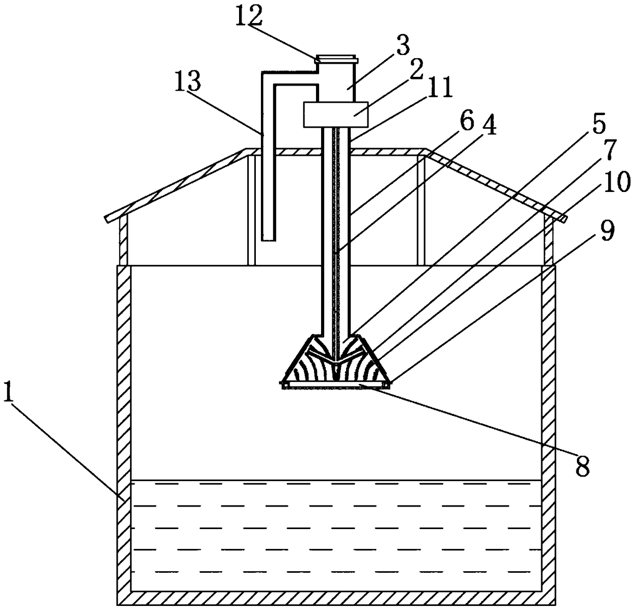
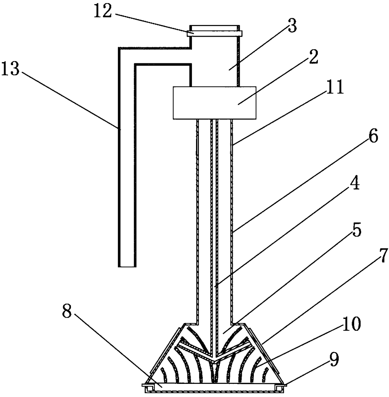
[0025] Such as figure 1 As shown, a self-condensing water reservoir includes a reservoir 1, an energy supply system 2, an air intake pipe 3, an air guide pipe 4, a self-condensing chamber 5, an exhaust pipe 6, a semiconductor cooling chip 7, and a water storage tank 8 , drainage pipe 9, deflector 10 and exhaust port 11; the ceiling of described reservoir 1 is equipped with the energy supply system 2 that is used for generating electricity and compressed air enters air guide pipe 4, and described energy supply system 2 includes a vertical-axis wind generator, a fan and a power control module, and the power control module is electrically connected to the semiconductor cooling plate 7 and the vertical-axis wind generator respectively. The fan is connected to the main shaft of the vertical axis wind generator, and the rotation of the fan is driven by the rotation of the vertical axis wind generator, and the fan keeps blowing downward no matter whether it is forward or reverse; the...

Embodiment 2

[0029] The difference between the second embodiment and the first embodiment is that the energy supply system 2 uses solar energy as an energy source. The energy supply system 2 includes solar panels, fans and power control modules. The solar panels are laid on the On the ceiling of the reservoir 1 or near the reservoir 1, the fan is installed between the air intake pipe 3 and the air guide pipe 4, and the electric energy control module is electrically connected to the solar panel, the fan and the semiconductor refrigeration sheet 7 respectively. connect.


PUM


Abstract

The invention discloses a self-condensing reservoir. The self-condensing reservoir comprises a reservoir, an energy supply system, an air inlet pipe, a wind guide pipe, a self-condensing chamber, an exhausting pipe, semiconductor refrigerating plates and a water storage groove, wherein the energy supplying system is arranged on a ceiling of the reservoir, the air inlet pipe is connected to the topof the energy supplying system, the wind guide pipe is connected to the bottom of the energy supplying system; the exhausting pipe sheaths the outer part of the wind guide pipe, and the self-condensing chamber is fixedly connected to the lower end of the exhausting pipe; the water storage groove is arranged at the bottom part of the self-condensing chamber; the semiconductor refrigerating platesare close to the self-condensing chamber and are arranged on the side surfaces of the self-condensing chamber; the semiconductor refrigerating plates are electrically connected with the energy supplying system. The self-condensing reservoir disclosed by the invention has the beneficial effects that the independence is very strong, no limitation of hard conditions such as regions and terrains and the like are caused, and the worry about water sources can be eliminated; water vapor in the air can be condensed for multiple times, so that the efficiency is high; environmental-friendly wind energyand solar energy are adopted as power sources, so that any pollution to the environment can not be caused; the whole structure is simple, the installation is convenient and the use prospect and the promotion prospect are good.

Description

technical field [0001] The invention belongs to the technical field of water storage tanks, in particular to a self-condensing water storage tank. Background technique [0002] Existing reservoirs generally add water to the reservoir by pumping water. If the water pump is broken or the water pipe bursts, it will cause inconvenient water supply, and the water can only be used after the problem is solved; this situation is very important for remote areas. It is especially serious in areas where there is a lack of water or water, and such a situation can only wait for rescue. In the prior art, there is a device for automatically taking water in the desert. Its main principle is to bury a water storage device in the desert, and the air is drawn into the water storage device by a fan. Due to the temperature difference between the inside and the outside, the air The water vapor in the water will condense into water in the water storage device, thus realizing the effect of automat...

Claims


Application Information

Patent Timeline
Patent Type & Authority Applications(China)
IPC IPC(8): E03B3/28E03B11/00
CPCE03B3/28E03B11/00
Inventor 李森陈庚文沈志滔
Owner 广西芸耕科技有限公司
Why Eureka
Try Eureka