
Combined sleeve spanner

A technology of combining sleeves and sleeves, applied in the directions of wrenches, screwdrivers, manufacturing tools, etc., can solve the problems of carrying tools and inconvenient operation and construction, and achieve the effects of increasing thickness, improving work efficiency, and reducing the angle of rotation and reset

Inactive Publication Date: 2018-08-07
李梦丽
View PDF0 Cites 5 Cited by
  • Summary
  • Abstract
  • Description
  • Claims
  • Application Information

AI Technical Summary

Problems solved by technology

[0003] However, the existing socket wrenches usually have a socket of one specification that can only screw the bolts and nuts of the corresponding specifications. If you want to screw the bolts and nuts of multiple specifications, you must be equipped with socket wrenches of various specifications. The workplace where the bolts and nuts of the specified specifications bring a lot of inconvenience to carrying tools and operating construction

Method used


Image

  • Combined sleeve spanner
  • Combined sleeve spanner
  • Combined sleeve spanner

Examples


Embodiment 1

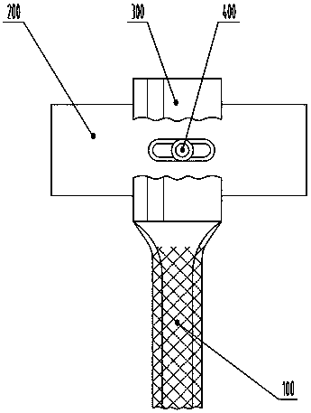
[0036] see figure 1 , in the figure, the combination socket wrench of the present invention includes a handle 100 and a socket assembly 200, which is used to connect the unidirectional torque driver 300 between the end of the handle and the middle part of the outer sleeve surface, and is used for the outer sleeve and each inner sleeve. Sleeve relative sliding and positioning relative sliding and positioning mechanism 400 etc. The outer sleeve and each inner sleeve are assembled together through a relative sliding and positioning mechanism, and the length of the outer sleeve and each inner sleeve is the same.

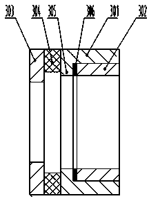
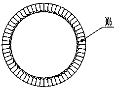
[0037] see Figure 2-3 , in the figure, the one-way torque driver 300 includes an outer ratchet ring 301 and an inner ratchet ring 302 that are matched inside and outside along the axial direction, wherein the inner ratchet ring is fixedly connected with the outer sleeve 201, and one end of the outer ratchet ring is radially And a boss 305 is arranged inwardly, and the...

Embodiment 2

[0041] see Figure 7 , the structure of this embodiment is similar to that of Embodiment 1, and the same numbers in the figure represent the same meaning, and the same parts in the structure of the two will not be repeated here. The sleeve assembly 200 , and the specifications of the sleeve assembly 200 at both ends of the handle 100 are configured in a cross-spaced specification. For example: if a set of combination socket wrench is designed for bolts and nuts of 10mm, 11mm, 12mm, 14mm, 15mm, 17mm, 19mm, 22mm, 24mm, the hexagonal combination socket at one end of the handle can be arranged from the inside to the outside. It is 10mm, 12mm, 14mm, 16mm, 22mm, and the hexagonal combination sleeve at the other end of the handle is arranged from inside to outside in 11mm, 13mm, 15mm, 19mm, 24mm. Arranged in intersecting intervals. Compared with the first embodiment, this embodiment can increase the thickness and mechanical strength of each sleeve in the sleeve assembly, which is b...

Embodiment 3 4

[0044] Present embodiment figure is not drawn. Embodiments 3 and 4 are similar in structure to Embodiments 1 and 2 respectively, and the structurally identical parts will not be repeated here. The difference lies in that the rest of the inner sleeve and Axial slide grooves are correspondingly provided on both sides of the outer sleeve, and the positioning spring is set on the positioning stroke-limiting pin, and together with the positioning stroke-limiting pin, they are sequentially installed in the mounting hole and each axial slide groove on one side.

[0045] In this embodiment, relative to Embodiments 1 and 2, respectively, axial slide grooves are provided on both sides of the other inner sleeves and outer sleeves except the innermost inner sleeve, and the positioning spring sleeve and the positioning travel limit pin can be They are installed in the installation holes and axial chute on one side in turn. Compared with the first and second embodiments, the other inner sle...


PUM


Abstract

The invention belongs to the technical field of hand tools, and particularly relates to a combined sleeve spanner. The combined sleeve spanner comprises a handle and a sleeve assembly, wherein the sleeve assembly comprises an outer sleeve and a plurality of inner sleeves sleeved with the outer sleeve in sequence, the end portion of the handle is connected with the middle portion of the surface ofthe outer sleeve through a one-way torsion actuator, the one-way torsion actuator comprises an outer ratchet ring and an inner ratchet ring which are in matched and sleeved inside-out arrangement along an axial direction, the inner ratchet ring is fixedly connected with the outer sleeve, a lug boss is arranged along a radial direction at the inner side of one end of the outer ratchet ring, the inner side face of the lug boss is in matched and meshed with a corresponding end face of the inner ratchet ring through set ring-shaped ratchets, and corresponds to the end face of the end, where the lug boss is located, of the outer ratchet ring, the surface of the outer sleeve is provided with an axial locating part, and an elastic connecting part is arranged between the axial locating part and acorresponding end face of the outer ratchet ring; and the outer sleeve and each inner sleeve are assembled together through relative sliding and a locating mechanism. The combined sleeve spanner can be suitable for twisting various type of bolts and nuts, the application range is wide, the operation and use are flexible and convenient, the carrying and storage are convenient, the spanner is safe and reliable, and the working efficiency of users is improved.

Description

technical field [0001] The invention belongs to the technical field of hand tools, in particular to a combined socket wrench. Background technique [0002] The socket wrench is composed of a plurality of sockets with hexagonal or twelve-pointed holes and is equipped with various accessories such as handles and extension rods. It is especially suitable for screwing bolts or nuts with very narrow positions or deep depressions. Socket wrenches are generally attached with a set of socket heads of various specifications and swing handles, extension rods, universal joints, screwdriver joints, elbow handles, etc. for inserting hexagonal nuts. The socket head of the socket wrench is a concave hexagonal cylinder. The wrench is usually made of carbon structural steel or alloy structural steel. The head of the wrench has a specified hardness, and the middle and handle parts are elastic. There are metric and imperial sleeves. Although the concave shape of the sleeve is the same, the ou...

Claims


Application Information

Patent Timeline
Patent Type & Authority Applications(China)
IPC IPC(8): B25B13/06B25B13/46B25B23/00
CPCB25B13/06B25B13/465B25B23/00
Inventor 王俊生李梦丽
Owner 李梦丽
Learn More