Steel ladle decapping system
A technology for ladle and ladle car, which is applied in casting molten material containers, metal processing equipment, casting equipment, etc., can solve the problems of waste of energy consumption and large floor space.
- Summary
- Abstract
- Description
- Claims
- Application Information
AI Technical Summary
Problems solved by technology
Method used
Image
Examples
Embodiment 1
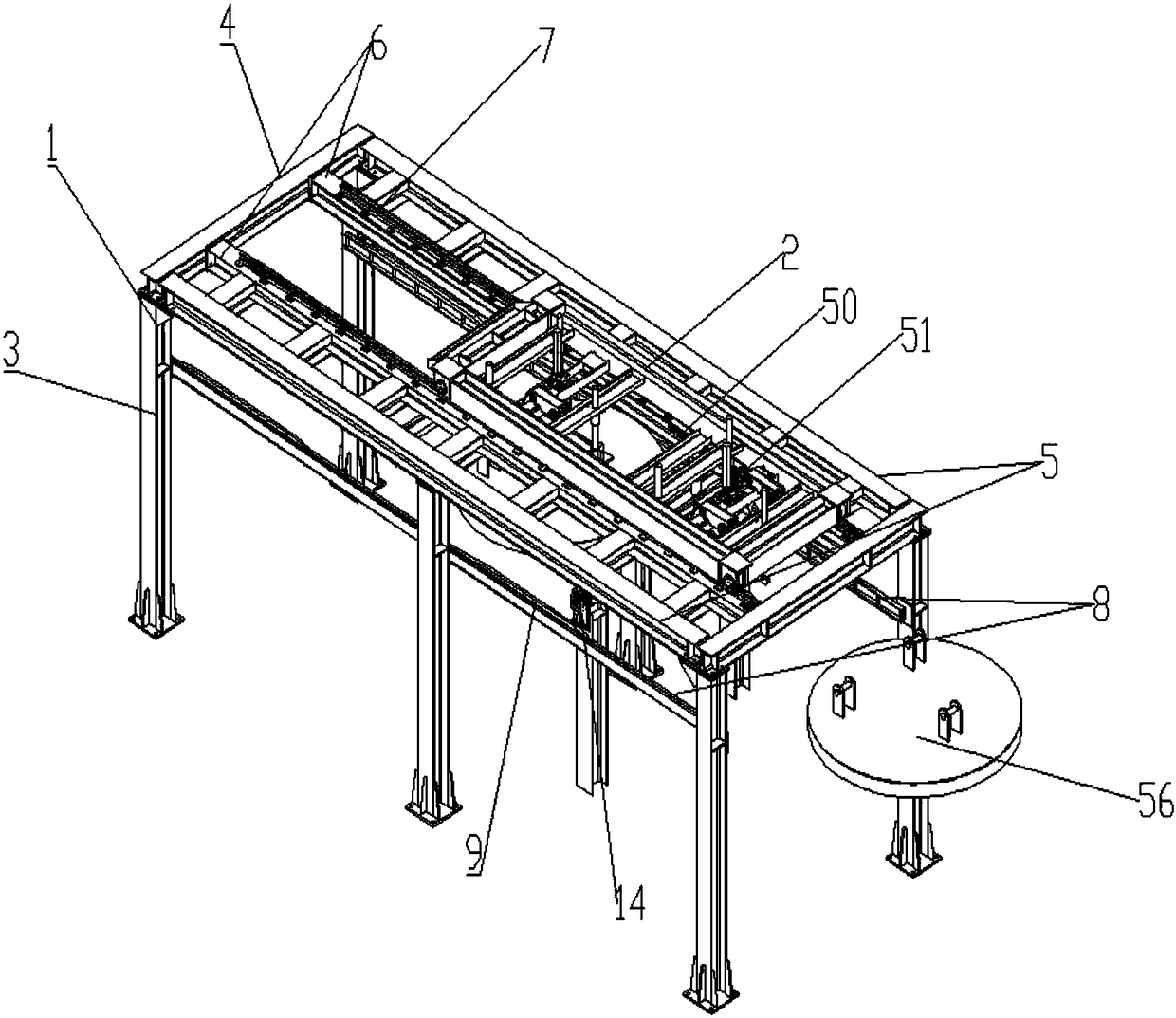
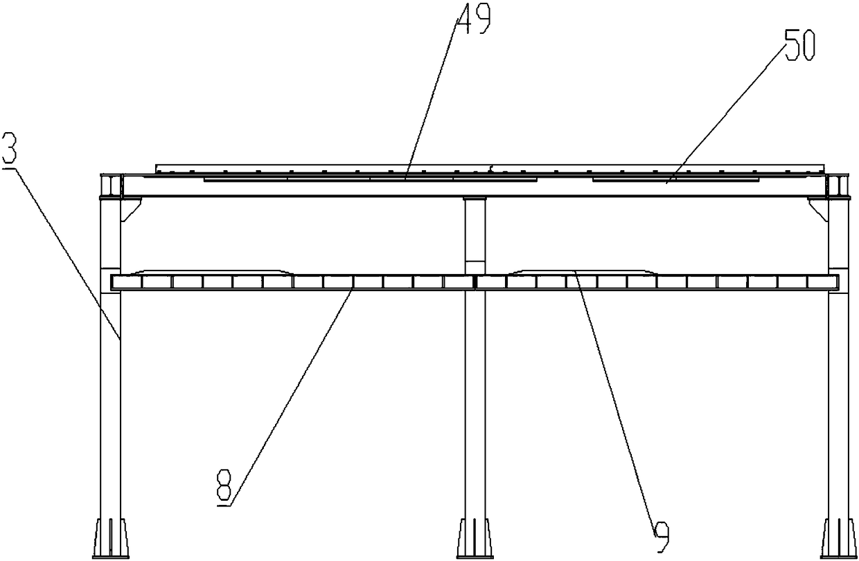
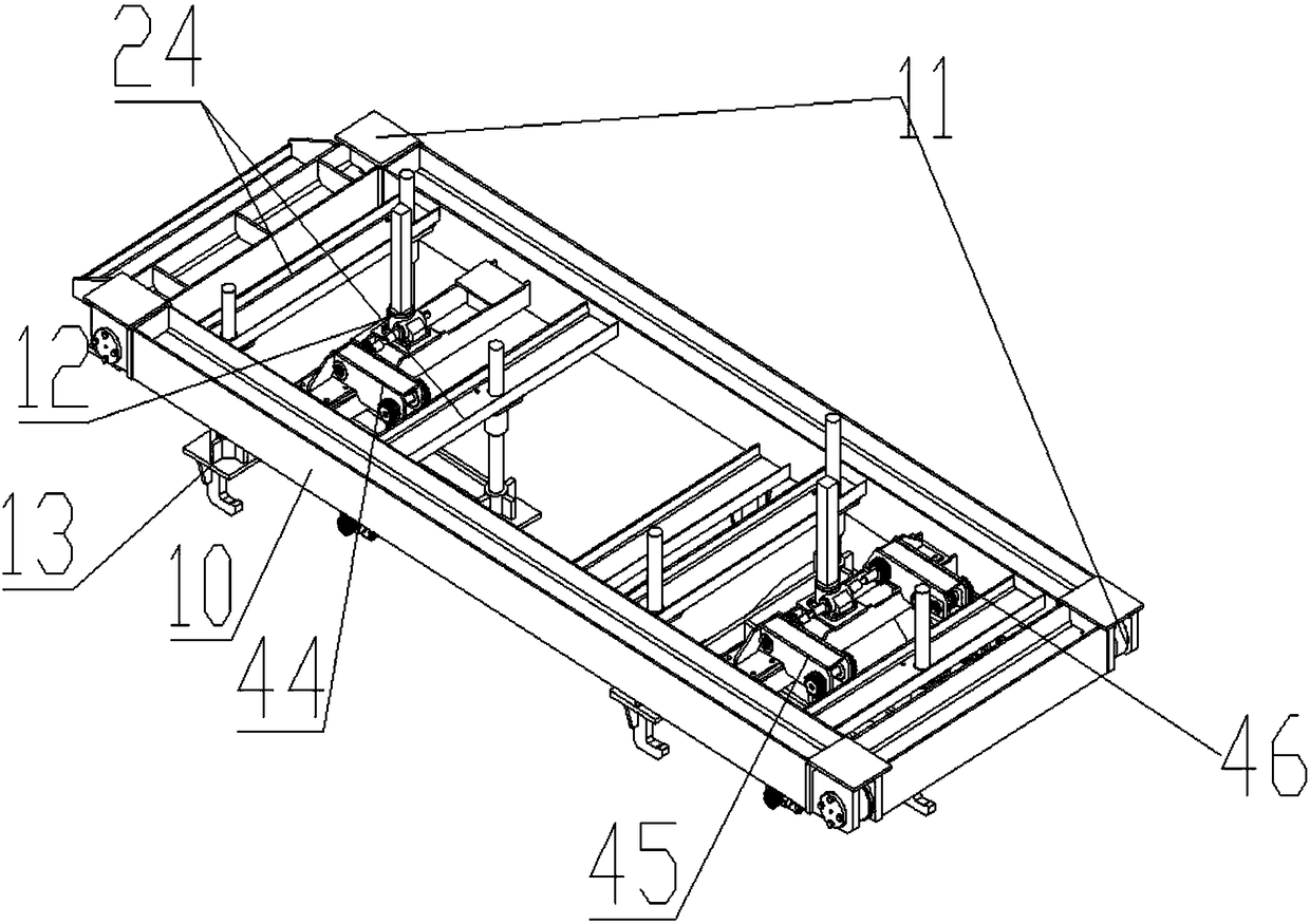
[0046] A ladle decapping system, comprising a gantry 1, a lifting trolley 2 placed on the upper end of the gantry 1, the gantry 1 includes a column 3, a beam 4 placed on the upper end of the column 3, and a track beam 5 connected to the beam 4 , the track 6 placed between the track beams 5 and connected with the column 3, the upper end of the track 6 is provided with a track pressure plate 7, the lower end of the track beam 5 is provided with a drive rack 51, and the lower end of the track 6 is provided with a drive track Support 8, the first and last ends of the drive track support 8 are connected with the column 3, the upper end of the drive track support 8 is connected with the drive track 9; 37. The ladle car runs in the gantry 1, driving the lifting trolley 2 to move horizontally on the gantry 1. Since there is a worm gear and worm screw lifting device 12 with the frame 10, the worm screw lifting device 12 is in the conversion of the movement power of the lifting trolley 2...
Embodiment 2
[0048] On the basis of Embodiment 1, the bottom of the trolley frame 10 is provided with a fixed seat 15, and the fixed seat 15 includes a first fixed seat 16, a second fixed seat 17, and the first fixed seat 16, the second fixed seat The lower end of seat 17 is respectively connected with the first ladle cover hook assembly 18 and the second ladle hook group 19; Take and place the ladle cover of the ladle car with two ladles, the first ladle cover hook assembly 18 and the second ladle hook group 19 are all provided with a hook base plate 20, and the hook base plate 20 is set There are three cover hooks 21, the middle part of the hook bottom plate 20 is connected with a lifting rod 22, and the other end of the lifting rod 22 is connected with the worm gear and worm screw lifting device 12, and the worm gear and worm screw lifting device 12 is connected with the fixing seat 15 upper ends are fixedly connected.
Embodiment 3
[0050] On the basis of Embodiment 2, the described worm gear screw lifting device 12 includes a guide rod 23, the fixed seat 15 is provided with a guide seat 24, and the guide rod 23 passes through the guide seat 24; The worm screw lifting device 12 also includes a lifting rod 22 connected to the hook base plate 20, a drive box 25 that is overlaid on the lifting rod 22, the side of the lifting rod 22 is provided with tooth lines, and the outer layer of the drive box 25 is Connected to the vehicle frame 10; the drive box 25 is equipped with a lifting drive gear meshed with the lifting rod 22, and the lifting meshing gear drives the meshing lifting rod 22 to move up and down under the power transmission of the lifting trolley 2, thereby realizing The first ladle cover hook assembly 18 and the second ladle hook group 19 are used to take and put the lid on the ladle car, wherein the guide rod 23 connected to the hook bottom plate 20 slides in the guide seat 24 under the drive of th...
PUM
 Abstract
Description
Claims
Application Information
 - R&D
- Intellectual Property
- Life Sciences
- Materials
- Tech Scout
- Unparalleled Data Quality
- Higher Quality Content
- 60% Fewer Hallucinations
Browse by: Latest US Patents, China's latest patents, Technical Efficacy Thesaurus, Application Domain, Technology Topic, Popular Technical Reports.
© 2025 PatSnap. All rights reserved.Legal|Privacy policy|Modern Slavery Act Transparency Statement|Sitemap|About US| Contact US: help@patsnap.com


