Imaging method and device for hydroxyapatite
A technology of hydroxyapatite and imaging method, which is applied in the field of spectral imaging, can solve the problems that the distribution shape range of hydroxyapatite cannot be determined, and the shape and size of the image cannot be seen, so as to achieve the effect of convenient and simple research, convenient and accurate imaging
- Summary
- Abstract
- Description
- Claims
- Application Information
AI Technical Summary
Problems solved by technology
Method used
Image

Examples
Embodiment 1
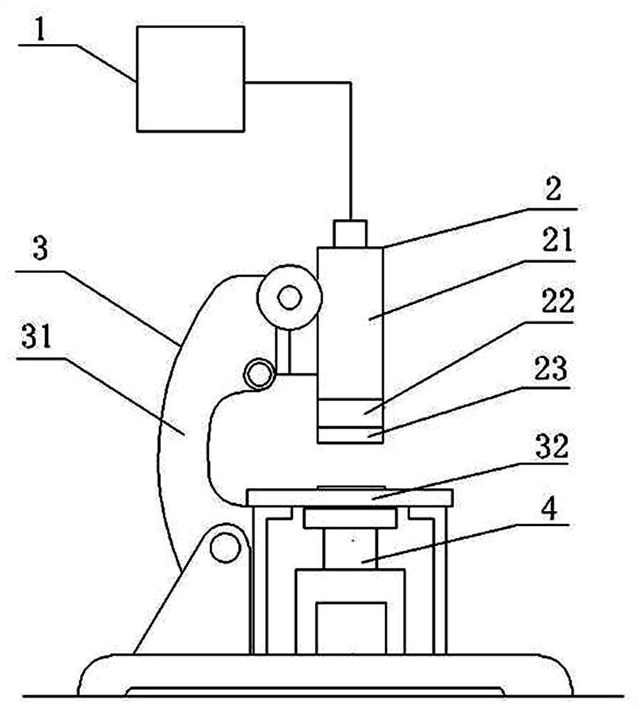
[0029] like figure 1 As shown, the invention provides a kind of imaging method for hydroxyapatite, it is characterized in that: this method is realized by following steps:
[0030] Step 1: Prepare the slice and device, make the sample into a slice with a thickness of 2-4mm, place the slice on the stage, move the camera lens to align with the slice, and can cover the size of the slice, and can receive all the scattering of the slice Light wave, adjust the position of the laser so that the laser located below the slice is aligned with the slice, and the light wave can better enter the camera lens after passing through the slice.
[0031] Step 2: Once imaging, when the laser is turned off, the light wave signal scattered by the slice and the surrounding environment passes through the optical filter on the camera. The cut-off depth of the filter is OD6, the central wavelength is 960nm, and the cut-off depth is OD6. The cut-off band transmittance of the filter is 0.0001%. The larg...
Embodiment 2
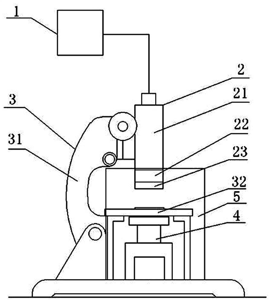
[0044] like figure 2 As shown, the technical solution of this embodiment can refer to Embodiment 1, but the difference from Embodiment 1 is that this embodiment adds a darkroom 5, the darkroom 5 is installed at the bottom of the support device 3, and the darkroom 5 is provided with a load stage 32, camera lens 22 and laser device 4, this darkroom separates the sample, object stage 32, camera lens 22 and laser device 4 from other surrounding environments, removes the influence of light waves scattered by other surrounding environments on infrared imaging, and makes subtraction The final infrared image is clearer, the effect is better, the difficulty of edge sharpening is reduced, the operation is more convenient, and the result is more accurate.
Embodiment 3
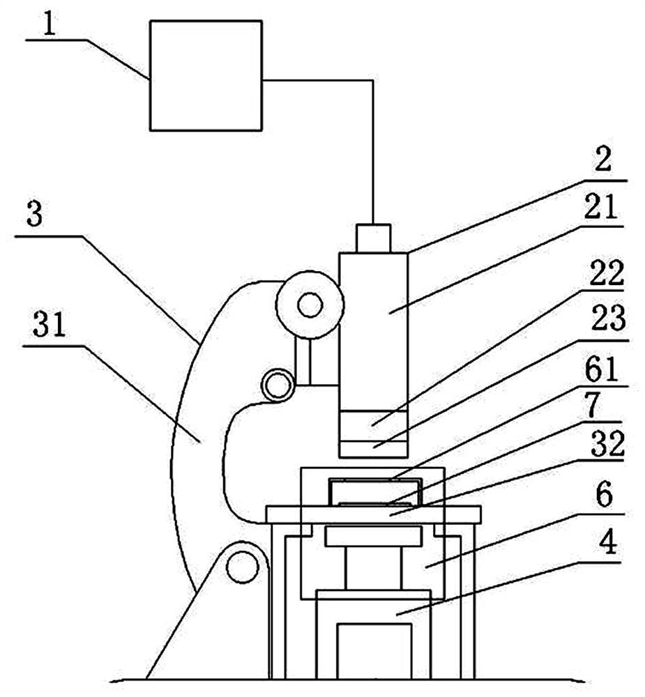
[0046] like image 3 As shown, the technical solution of this embodiment can refer to Embodiment 1, but the difference from Embodiment 1 is that this embodiment adds a heat absorbing device 6, which is installed on the laser 4 and is compatible with the laser 4. The heating components are connected, and the laser 4 will generate heat energy when it emits light, and the heat energy will radiate to the outside world with different wavelengths of infrared rays. Among them, there are infrared rays with wavelengths that can pass through the filter, so this part of the wavelength of infrared rays will have an impact on the test. , which is the thermal noise usually mentioned, the heat absorbing device 6 is a heat conducting device made of a diamond sheet and a copper sheet, the thermal conductivity of diamond is the highest in nature, and the diamond sheet is connected with the heat-generating components in the laser 4, and the copper sheet It is connected to the diamond sheet, and ...
PUM
| Property | Measurement | Unit |
|---|---|---|
| thickness | aaaaa | aaaaa |
| wavelength | aaaaa | aaaaa |
| wavelength | aaaaa | aaaaa |
Abstract
Description
Claims
Application Information
 - Generate Ideas
- Intellectual Property
- Life Sciences
- Materials
- Tech Scout
- Unparalleled Data Quality
- Higher Quality Content
- 60% Fewer Hallucinations
Browse by: Latest US Patents, China's latest patents, Technical Efficacy Thesaurus, Application Domain, Technology Topic, Popular Technical Reports.
© 2025 PatSnap. All rights reserved.Legal|Privacy policy|Modern Slavery Act Transparency Statement|Sitemap|About US| Contact US: help@patsnap.com