Complex structural component defect optical fiber acoustic detection system and detection and imaging method thereof

A detection system, optical fiber acoustic technology, applied in measuring devices, using sound waves/ultrasonic waves/infrasonic waves to analyze solids, using sound waves/ultrasonic waves/infrasonic waves for material analysis, etc., can solve inaccurate positioning, affect probe sensitivity, and sound field energy transmission loss and other problems, to achieve the effects of high detection accuracy, fast computing and imaging speed, and high sensitivity

Pending Publication Date: 2021-01-22
HARBIN ENG UNIV
View PDF0 Cites 2 Cited by
  • Summary
  • Abstract
  • Description
  • Claims
  • Application Information

AI Technical Summary

Problems solved by technology

[0002] For the detection of three-dimensional complex components such as concave, convex, concave / convex surfaces, ultrasonic sensors are usually used for sound wave transmission detection, while traditional rigid ultrasonic probes cannot directly match the surface of the test piece, and sound wave reception is required through water coupling or wedge coupling , due to the difference in acoustic impedance between the couplant and the test piece, the energy of the acoustic field is lost when it is transmitted between the interface between the couplant and the test piece, which in turn affects the sensitivity of the probe, resulting in inaccurate defect positioning. The use of fiber gratings for acoustic detection avoids the above shortcomings

Method used


Image

  • Complex structural component defect optical fiber acoustic detection system and detection and imaging method thereof
  • Complex structural component defect optical fiber acoustic detection system and detection and imaging method thereof
  • Complex structural component defect optical fiber acoustic detection system and detection and imaging method thereof

Examples


specific Embodiment approach 1

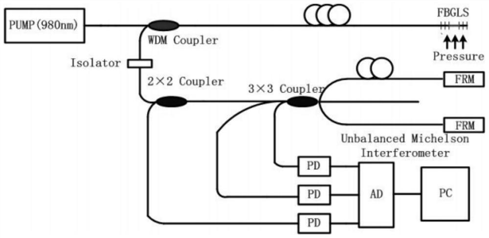
[0044] Specific Embodiment 1: In this embodiment, the optical fiber acoustic detection system for defects in complex structural parts includes an ultrasonic transducer array, an optical fiber sensing signal detection and demodulation system, and a computer imaging system; it is characterized in that:

[0045] The ultrasonic transducer array is fabricated as a fan-shaped phased array;

[0046] The optical fiber sensing signal detection and demodulation system includes a light source, a wavelength division multiplexer, a fiber laser sensor array, an unbalanced Michelson fiber interferometer, and a photodetector; the unbalanced Michelson fiber interferometer uses 2×2 couplers, 3×3 Composed of a coupler and a Faraday rotating mirror; the fiber laser sensor array is composed of four DFB lasers connected in series, the four DFB lasers share one optical path, and the four DFB lasers are arranged in a square.

[0047] In this embodiment, the pump laser enters four DFB lasers (distribu...

specific Embodiment approach 2

[0068] Embodiment 2: The difference between this embodiment and Embodiment 1 is that the length of the DFB laser is 5 cm. Other steps and parameters are the same as those in Embodiment 1.

[0069] In order to facilitate single longitudinal mode laser oscillation and facilitate packaging, this embodiment adopts a distributed feedback laser (DFB) with a length of 5 cm. It can be seen from formula (A1) that the change of the effective refractive index of the core region of the erbium-doped fiber or the change of the grating period will lead to the change of the operating wavelength of the DFB laser. When the DFB laser is subjected to external sound pressure, the strain generated by the sound pressure will change the effective refractive index of the fiber and the period of the grating. At this time, the change in the operating wavelength of the DFB laser can be determined by the following formula:

[0070]

[0071] where P 11 and P 12 is the photoelastic coefficient, ε z ,...

specific Embodiment approach 3

[0080] Embodiment 3: The difference between this embodiment and Embodiment 1 or 2 is that the side length of the squares arranged by DFB lasers is 8-20 cm. Other steps and parameters are the same as those in Embodiment 1 or 2.

[0081] The sound wave will attenuate when it propagates in the medium. During the propagation process, due to the diffusion of the wave front, the energy space will be diffused, so that the wave amplitude will attenuate with the increase or decrease of the distance. This attenuation is called geometric attenuation. Due to the scattering effect of the particles in the medium, the energy of the sound wave in the original propagation direction is reduced, resulting in a significant attenuation of the wave amplitude with the increase of the propagation distance. The loss of sound waves in the medium includes the dissipation caused by viscous force, heat conduction and relaxation process. Heat conduction dissipation is due to the fact that during the propa...


PUM

PropertyMeasurementUnit
Lengthaaaaaaaaaa

Abstract

The invention discloses a complex structural component defect optical fiber acoustic detection system and a detection and imaging method thereof, and relates to a structural component ultrasonic detection system and a detection and imaging method thereof. The complex structural component defect optical fiber acoustic detection system comprises an ultrasonic transducer array, an optical fiber sensing signal detection and demodulation system and a computer imaging system. The detection and imaging method is characterized by adopting the complex structural component defect optical fiber acousticdetection system and comprises the following steps that: 1, the ultrasonic transducer array and an optical fiber laser sensor array in the optical fiber sensing signal detection and demodulation system are located on the two sides of a detected complex structural component respectively; 2, the ultrasonic transducer array scans, and carries out optical fiber sensor modulation and demodulation signal conversion; and 3, imaging is conducted so as to detect the defects of the complex structural component. The measurement error of the sound velocity is within 3 meters; the maximum error is within the range of + / 4m / s; cracks of 5 mm*1 mm*5 mm can be distinguished, and flat-bottom holes of phi 1 mm*5 mm can be detected; and the imaging spatial resolution of the system is smaller than 2 mm, and the complex structural component defect optical fiber acoustic detection system has the advantages of being high in imaging calculation speed and the like.

Description

technical field [0001] The invention relates to an ultrasonic testing system for a configuration part and a testing and imaging method thereof. Background technique [0002] For the detection of three-dimensional complex components such as concave, convex, concave / convex surfaces, ultrasonic sensors are usually used for sound wave transmission detection, while traditional rigid ultrasonic probes cannot directly match the surface of the test piece, and sound wave reception is required through water coupling or wedge coupling , due to the difference in acoustic impedance between the couplant and the specimen, the energy of the acoustic field is lost when it is transmitted between the interface between the couplant and the specimen, which in turn affects the sensitivity of the probe and leads to inaccurate defect positioning. The use of fiber Bragg gratings for acoustic detection avoids the above shortcomings. Contents of the invention [0003] The invention proposes a detect...

Claims


Application Information

Patent Timeline
IPC IPC(8): G01N29/06G01N29/24
CPCG01N29/069G01N29/2418G01N2291/023G01N2291/0289
Inventor 刘盛春曹国昕陈雪峰杨占锋周海强
Owner HARBIN ENG UNIV
Why Eureka
Try Eureka