Fitting large field of view optical pod structure and working method based on flat glass

A large field of view and pod technology, which is applied to the structure and work field of large field of view optical pods based on flat glass fitting, and can solve problems such as the limitation of the forward field of view

Active Publication Date: 2020-04-17
FUJIAN FORECAM OPTICS CO LTD
View PDF4 Cites 0 Cited by
  • Summary
  • Abstract
  • Description
  • Claims
  • Application Information

AI Technical Summary

Problems solved by technology

However, the addition of a fairing not only protects the optical system, but also greatly restricts the forward field of view. The general field of view can only cover the range of -30° to 30° forward.

Method used


Image

  • Fitting large field of view optical pod structure and working method based on flat glass
  • Fitting large field of view optical pod structure and working method based on flat glass
  • Fitting large field of view optical pod structure and working method based on flat glass

Examples


Embodiment Construction

[0020] The present invention will be described in further detail below in conjunction with the accompanying drawings and specific embodiments.

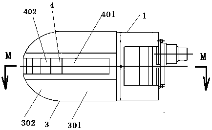
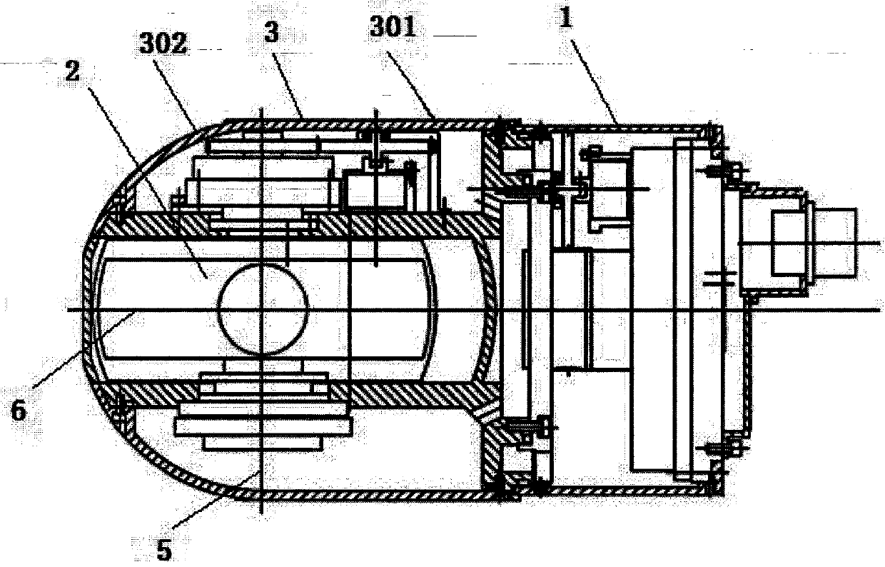
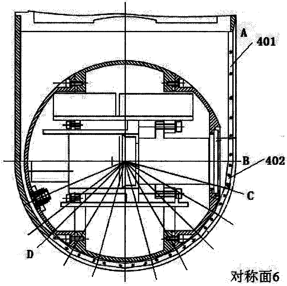
[0021] The present invention is based on the planar glass fitting large field of view optical pod structure, which includes a pod 1 and an optical camera device 2 inside the pod. The strip-shaped visible window 4 , the lens end 5 of the optical camera device 2 is facing the narrow strip-shaped visible window 4 . When the optical imaging device of the present invention moves in pitch, the movement of the optical axis forms a strip, and when the azimuth rotates, the virtual strip formed by the pitch movement moves synchronously with the lens and is relatively static. Theoretically, it can The optical rectification effect is realized by using such a narrow strip protection method.

[0022] Further, in order to design rationally, the end of the pod includes a cylindrical section 301 and a hemispherical section 302, and the partial sectio...


PUM


Abstract

The invention relates to a large-view-field optical nacelle structure based on plain glass fitting and a working method of the large-view-field optical nacelle structure. The structure is characterized in that the large-view-field optical nacelle structure based on plain glass fitting comprises a nacelle and an optical photographing device arranged in the nacelle, a narrow strip-shaped visual window is formed in the end head of the nacelle, multiple sheets of a transparent material are sequentially spliced to form the narrow strip-shaped visual window, and the lens end of the optical photographing device directly faces the narrow strip-shaped visual window. By the adoption of the large-view-field optical nacelle structure based on plain glass fitting, performance uniformity and optical distribution evenness of a whole optical system in a whole view angle range can be achieved. The strength of a whole fairing is much larger than that of a semicircular fairing.

Description

Technical field: [0001] The invention relates to a flat glass-based fitting large-field optical pod structure and working method. Background technique: [0002] The pod refers to a streamlined nacelle section that is installed with certain airborne equipment or weapons and is hung under the fuselage or wing. It can be fixedly installed (such as an engine pod) or detachable (such as a weapon pod). The addition of pods can make the aircraft have functions that it does not have. The addition of pods usually requires the support of onboard electronic equipment and consideration of the overall aerodynamics of the aircraft. [0003] The common pod is installed under the belly of the aircraft, and is relatively large in size. In order to be able to resist factors such as wind and vibration, the pod is relatively large in size. The pod mainly includes an azimuth rotation part and a pitch rotation part. Because the azimuth and rotation axis of the pod is perpendicular to the belly ...

Claims


Application Information

Patent Timeline
Patent Type & Authority Patents(China)
IPC IPC(8): B64D47/00B64D47/08
CPCB64D47/00B64D47/08
Inventor 车国锋王颖军侯艳萍林春生肖维军
Owner FUJIAN FORECAM OPTICS CO LTD
Why Eureka
Try Eureka