
Outer discharging type pressure regulating device for circulating water pump

The technology of a pressure regulating device and a circulating water pump is applied to the components, pumps, and pump elements of the pumping device for elastic fluids, which can solve the problem that the water bubble occupies the space of the pipe coil, the dynamic resistance of fluid transportation, and the high compressibility of the gas. and other problems, to achieve the effect of good gas-water separation effect, small conveying resistance and simple structure

Inactive Publication Date: 2018-07-27
DONGGUAN UNIV OF TECH +1
View PDF0 Cites 2 Cited by
  • Summary
  • Abstract
  • Description
  • Claims
  • Application Information

AI Technical Summary

Problems solved by technology

In addition, the causes of excessive air bubbles at the water pump outlet include the following reasons: the temperature of the water flow of the inlet pump increases in summer; the sealing of the water inlet and the water pipe of the water pump is not good, causing air to enter the pump; Under the environment, the pipe wall corrodes and has holes. When these holes are exposed to the water surface, the air enters the water pipe from the holes.
[0004] A large number of water bubbles are mixed with water in the pipeline. On the one hand, the gas is highly compressible, and the gas in the local flow area where the pressure suddenly increases sharply shrinks, or even annihilates. This sudden volume change in space will cause vibration and serious noise; on the other hand On the one hand, water bubbles occupy a certain amount of space in the pipe coil, which creates great dynamic resistance to fluid delivery

Method used


Image

  • Outer discharging type pressure regulating device for circulating water pump
  • Outer discharging type pressure regulating device for circulating water pump
  • Outer discharging type pressure regulating device for circulating water pump

Examples


Embodiment 1

[0034] This embodiment provides a leaking type circulating water pump pressure regulating device, which can quickly separate the water and gas in the pipeline.

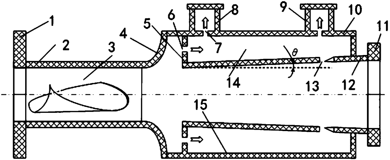
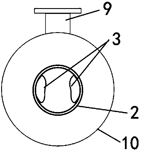
[0035] see figure 1 and figure 2 As shown, in this embodiment, the leakage type circulating water pump pressure regulating device is a hollow cylindrical cylinder, which includes a swirl tube 2 and a pressure regulating tube 15 connected to the swirl tube 2 .

[0036] The inner diameter of the swirl tube 2 is smaller than the inner diameter of the pressure regulating tube 15 , and a separation component 3 for separating gas and water is fixedly arranged in the swirl tube 2 .

[0037] Specifically, the separation component 3 is a spiral guide vane, and the spiral guide vane is fixedly connected to the inner wall of the swirl tube 2 .

[0038] When the water pump works, the water in the pipeline flows from the swirl pipe 2 to the pressure regulating pipe 15 and is output from the pressure regulating pipe 15 . At thi...

Embodiment 2

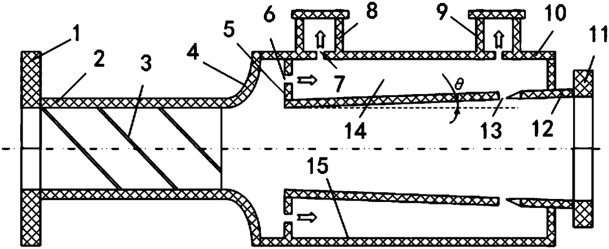
[0050] see image 3 , the separating component 3 is the thread on the inner wall of the swirl tube 2 .

[0051] The inner wall thread is a triangular or rectangular right-handed thread, and the inclination angle of the inner wall thread is 50° to 60°, which can avoid excessive flow resistance and make the gas and water separation effect better.

Embodiment 3

[0053] see Figure 4 and Figure 5 ,, the shape of the sealing plate 5 is arc-shaped, preferably arc-shaped. The suction hole 6 is opened in the arc-shaped sealing plate 5, which can further enhance the ability to separate gas and water.


PUM


Abstract

The invention discloses an outer discharging type pressure regulating device for a circulating water pump. The device is a hollow cylindrical barrel body, wherein the hollow cylindrical barrel body comprises a cyclone pipe, and a pressure regulating pipe which is connected to the cyclone pipe; the inside diameter of the cyclone pipe is less than that of the pressure regulating pipe; a separating part for separating air and water is arranged in the cyclone pipe, and the separating part is a spiral flow guide blade which is fixedly connected to the inner wall of the cyclone pipe. According to the device, the separating part for separating air and water is arranged in the cyclone pipe and is capable of forcibly forming spiral flow through water stream, and the purpose of separating air and water is achieved through the centrifugal force; and meanwhile, when the separated air enters the pressure regulating pipe, the air enters a suction hole and then enters a through hole and finally is exhausted through an exhaust valve at the front end or the exhaust valve at the tail end; the device is simple in structure, hard to vibrate, low in noise, and small in fluid conveying resistance.

Description

technical field [0001] The invention relates to the technical field of water pumps, in particular to a leaking type circulating water pump pressure regulating device. Background technique [0002] Bubbles are inevitably generated when the water pump is working. The vaporization pressure of clear water at room temperature is about 3.17Kpa (water temperature is 25°C). When the local pressure inside the pump is lower than the vaporization pressure, bubbles will be generated there. For cavitation. [0003] The pressure at the inlet of the impeller is the lowest, and the cavitation phenomenon is the most serious. At the same time, the oxygen dissolved in the water will escape, so the water sent by the pump contains a lot of water bubbles. In addition, the causes of excessive air bubbles at the pump outlet include the following reasons: the temperature of the water flow of the inlet pump increases in summer; the sealing of the water inlet and the water pipe of the water pump is n...

Claims


Application Information

Patent Timeline
Patent Type & Authority Applications(China)
IPC IPC(8): F04D29/66F04D29/44F04D29/00
CPCF04D29/669F04D29/007F04D29/445
Inventor 肖汉敏陈捷超陈佰满
Owner DONGGUAN UNIV OF TECH
Learn More