
Single-circulation two-stage LNG cold energy power generation and ice making method and system

A single cycle, cold energy technology, applied in the direction of ice making, ice making, fluid circulation arrangement, etc., can solve the problems of poor economic benefits, high investment costs, low single-stage utilization efficiency, etc., to simplify the process and equipment composition, reduce Effects of investment and floor area, saving heat and operating costs

Active Publication Date: 2018-07-27
江苏中圣压力容器装备制造有限公司
View PDF10 Cites 4 Cited by
  • Summary
  • Abstract
  • Description
  • Claims
  • Application Information

AI Technical Summary

Problems solved by technology

[0005] The problems of the above LNG cold energy utilization schemes are that single-stage utilization efficiency is low, and a lot of LNG cold energy has not been fully utilized; two-stage power generation or multi-stage power generation systems are huge, with many equipments, high investment costs, and poor economic benefits

Method used


Image

  • Single-circulation two-stage LNG cold energy power generation and ice making method and system

Examples


Embodiment 1

[0034] The LNG components (mole fraction) provided by the LNG receiving station are: methane 99.78%, ethane 0.1%, nitrogen 0.12%; the flow rate is 200t / h, and the organic working fluid used in the Rankine cycle power generation system is ethane.

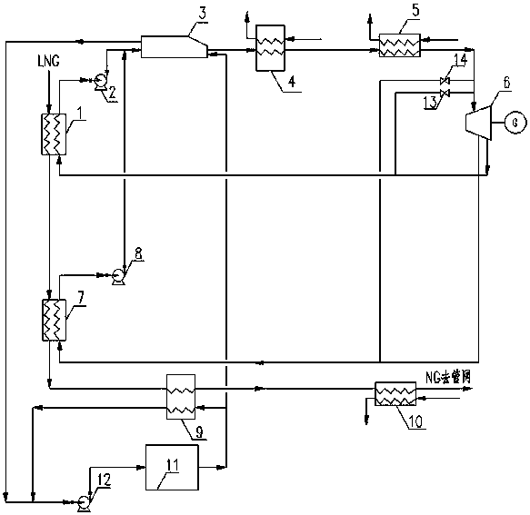
[0035] Such as figure 1 As shown, a single-cycle two-stage LNG cold energy power generation and ice-making method: LNG at -155 ° C is pressurized to 9.8 MPa by a booster pump, and the first condenser 1 and the turbine power generation unit 6 come out Low-pressure organic working medium steam heat exchange, recycling LNG cold energy in the low-temperature section (-155°C ~ -102°C) to obtain low-pressure organic working medium liquid; The working medium steam is heat-exchanged in the second condenser 7, and the LNG temperature cold energy in the medium temperature section (-102°C ~ -47°C) is recovered to obtain medium-pressure organic working medium liquid; after heat exchange with LNG, the low-pressure organic working medium is conden...


PUM


Abstract

The invention discloses a single-circulation two-stage LNG cold energy power generation and ice making method and system. The single-circulation two-stage LNG cold energy power generation and ice making method comprises the following steps that low-pressure organic working medium steam discharged by a turbo-generator unit and LNG input into an LNG storage tank are subjected to heat exchanging to recover LNG cold energy at the low-temperature stage; medium-pressure organic working medium steam pumped out from the turbo-generator unit and the LNG subjected to primary heat exchanging are subjected to heat exchanging to recover LNG cold energy at the medium-temperature stage; organic working medium liquid formed through heat exchanging liquefying sequentially passes through a working medium-refrigerant heat exchanger, an evaporator and a superheater to be subjected to heat exchanging to become superheating organic working medium steam, and the superheating organic working medium steam is sent into the turbo-generator unit to apply work and generate power; meanwhile the LNG subjected to two-stage heat exchanging is subjected to heat exchanging again to exchange the surplus cold energy at the high-temperature stage, and the LNG subjected to three-time heat exchanging is heated through an LNG heater and then sent to a natural gas outward-transporting pipe network; and refrigerants during three-time heat exchanging return to a refrigerating device to make ice. According to the single-circulation two-stage LNG cold energy power generation and ice making method, the procedure is simplified, investment and the occupied area are reduced, and the heat and operating cost need by LNG gasification can be saved.

Description

technical field [0001] The present invention relates to the technical field of cascade utilization of LNG (liquefied natural gas) cold energy, specifically a method and system for single-cycle, two-stage LNG cold energy power generation and ice making. The method combines Rankine power generation with LNG cold energy grades. Combined with ice making, a cascade utilization system of LNG cold energy is established. Background technique [0002] With the rapid development of LNG trade, countries all over the world are exploring the ways and methods of LNG cold energy utilization. Japan is in the leading position in the use of cold energy in the world. In addition to being used in conjunction with power plants, there are more than 20 sets of independent LNG cold energy utilization equipment, including air separation devices, dry ice making devices, deep freezing warehouses, low-temperature Lang Ken cycle independent power generation unit. Among the existing LNG cold energy tec...

Claims


Application Information

Patent Timeline
Patent Type & Authority Applications(China)
IPC IPC(8): F01K25/10F01K17/06F01D15/10F25C1/00F25B41/00
CPCF01D15/10F01K17/06F01K25/10F25C1/00F25B41/40Y02P60/85
Inventor 郭宏新刘世平阚苏玉刘丰刘洋高辉
Owner 江苏中圣压力容器装备制造有限公司
Learn More