Deceleration strip energy utilization device based on hydraulic loop

A technology of hydraulic circuit and deceleration belt, applied in the direction of fluid pressure actuating device, fluid pressure actuating system components, servo motor components, etc., can solve the problems of low power generation efficiency and poor stability, improve lifespan and reduce shock and vibration , The effect of stable power generation for a long time

Active Publication Date: 2018-07-24
NORTHEASTERN UNIV
View PDF16 Cites 2 Cited by
  • Summary
  • Abstract
  • Description
  • Claims
  • Application Information

AI Technical Summary

Problems solved by technology

[0006] Aiming at the existing technical problems, the present invention provides a deceleration belt energy utilization device based on a hydraulic circuit, which can solve the problems of low power generation efficiency and poor stability in the prior art

Method used


Image

  • Deceleration strip energy utilization device based on hydraulic loop
  • Deceleration strip energy utilization device based on hydraulic loop

Examples


Embodiment Construction

[0033] In order to better explain the present invention and facilitate understanding, the present invention will be described in detail below through specific embodiments in conjunction with the accompanying drawings.

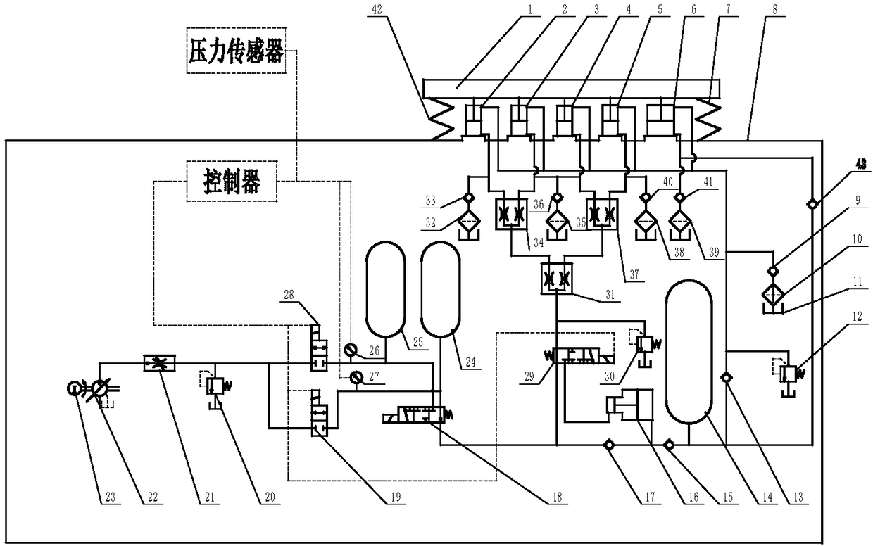
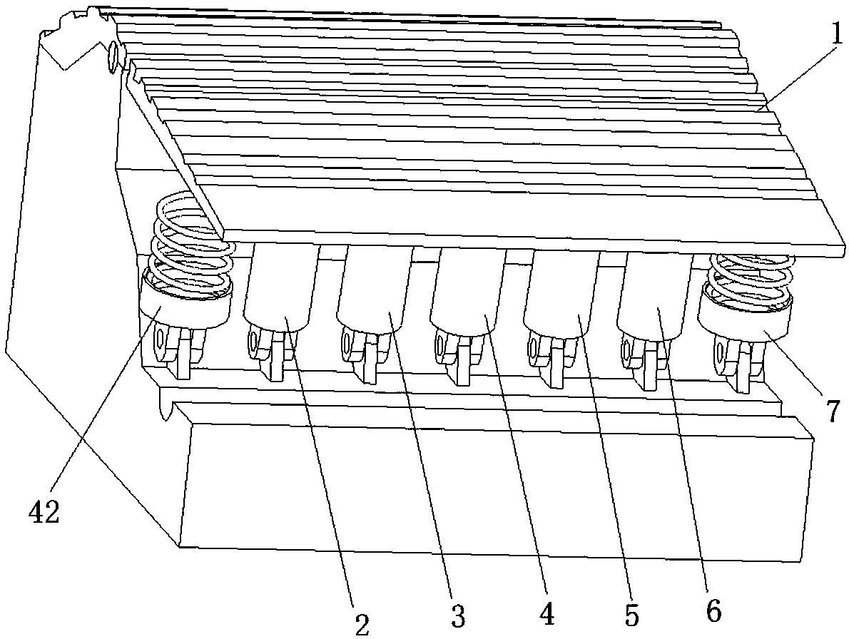
[0034] Such as figure 1 , figure 2 As shown, the present invention discloses a speed bump energy utilization device based on a hydraulic circuit, which includes a speed bump energy collection device and a power generation module.

[0035] The speed bump energy collection device includes a speed bump 1, a speed bump reset device and a plurality of hydraulic cylinders arranged under the speed bump.

[0036] A plurality of hydraulic cylinders are divided into two parts, wherein, the lower chamber of the first part of the hydraulic cylinder communicates with the first valve port of the first three-position four-way solenoid valve 29 through the confluence valve, and the lower chamber of the second part of the hydraulic cylinder communicates with the accumulator ...


PUM


Abstract

The invention belongs to the technical field of energy recovery, and particularly relates to a deceleration strip energy utilization device based on a hydraulic loop. The deceleration strip energy utilization device based on the hydraulic loop comprises a deceleration strip energy collection device and a power generation module, wherein the deceleration strip energy collection device comprises a deceleration strip, a deceleration strip resetting device and a plurality of hydraulic cylinders arranged below the deceleration strip; the hydraulic cylinders, electromagnetic valves, an energy storage device, energy accumulators, a hydraulic motor and an oil tank form the hydraulic loop; and the device further comprises a controller and a pressure detection device, wherein the pressure detectiondevice is used for detecting the pressure of the outlet end of the first energy accumulator and the outlet end of the second energy accumulator, and the pressure detection device and the electromagnetic valve are electrically connected with the controller. According to the deceleration strip energy utilization device, the common energy accumulators in hydraulic pressure are utilized to fully playthe role of the energy accumulators, and by means of pressure sensors and control of the controller, high-energy storage is achieved; and furthermore, the flow is effectively controlled, long-time stable power generation is achieved, and the trend of the current industrial automation is met.

Description

technical field [0001] The invention belongs to the technical field of energy recovery, and in particular relates to an energy utilization device for a speed bump based on a hydraulic circuit. Background technique [0002] Today, with the development of Chinese society, road transport of goods has become the mainstream choice for passengers to travel short distances. At toll gates or inspection gates, passing vehicles in centralized control stations, etc., speed bumps are widely used as facilities for mandatory speed control, and the vibration energy is not used when motor vehicles pass, which will cause energy loss in vain. [0003] The road deceleration belt power generation device makes full use of idle energy, and utilizes the energy generated when the vehicle passes the deceleration belt, which can provide a certain amount of backup energy guarantee for the automatic service equipment, and also reduce the power supply of the power supply system to street lights, signal ...

Claims


Application Information

Patent Timeline
Patent Type & Authority Applications(China)
IPC IPC(8): F15B21/14F15B1/02F15B13/02
Inventor 陈延炜李小彭陈达张海洋陈曦赵海东朱俊汶
Owner NORTHEASTERN UNIV
Why Eureka
Try Eureka