Anti-blocking automatic forceps body blanking continuous drilling and milling machine tool

A technology for automatic cutting and machining of machine tools, applied in metal processing, manufacturing tools, other manufacturing equipment/tools, etc., can solve the problems of unfavorable continuous processing production, unfavorable automated production, high processing and maintenance costs, and achieve convenient automatic sorting and processing. The effect of facilitating automatic processing and saving manpower and material resources

Inactive Publication Date: 2018-07-24
SHAODONG HEXIE HARDWARE ELECTROMECHANICAL CO LTD
View PDF0 Cites 1 Cited by
  • Summary
  • Abstract
  • Description
  • Claims
  • Application Information

AI Technical Summary

Problems solved by technology

[0003] In the existing pliers head processing technology, when manufacturing pliers, the four elements on the pliers head are completed by two processes and divided into eight processing stations, and the left pliers body is clamped four times and processed four times. station; the right pliers body has four clamping and four processing stations; and the existing technology is mostly manual clamping, resulting in low production efficiency and high labor intensity
[0004] The application number submitted by the applicant on January 13, 2018 is 2018200545717, and the name is a continuous drilling and milling machine tool with automatic blanking of the pliers body. During the process, since the push plate and the processing platform are both solid structures, processing chips are easy to accumulate, causing blockage or jamming, which is not conducive to continuous processing and production. In the experiment, when high-pressure air is used to blow chips, the chip collection After processing 1000-2000 pliers bodies, it is necessary to stop the machine to clean up the cutting chips, so the cost of processing and maintenance is high, which is not conducive to automatic production

Method used


Image

  • Anti-blocking automatic forceps body blanking continuous drilling and milling machine tool
  • Anti-blocking automatic forceps body blanking continuous drilling and milling machine tool
  • Anti-blocking automatic forceps body blanking continuous drilling and milling machine tool

Examples


Embodiment Construction

[0050] In order to enable those skilled in the art to better understand the technical solution of the present invention, the present invention will be described in detail below in conjunction with the accompanying drawings. The description in this part is only exemplary and explanatory, and should not have any limiting effect on the protection scope of the present invention. .

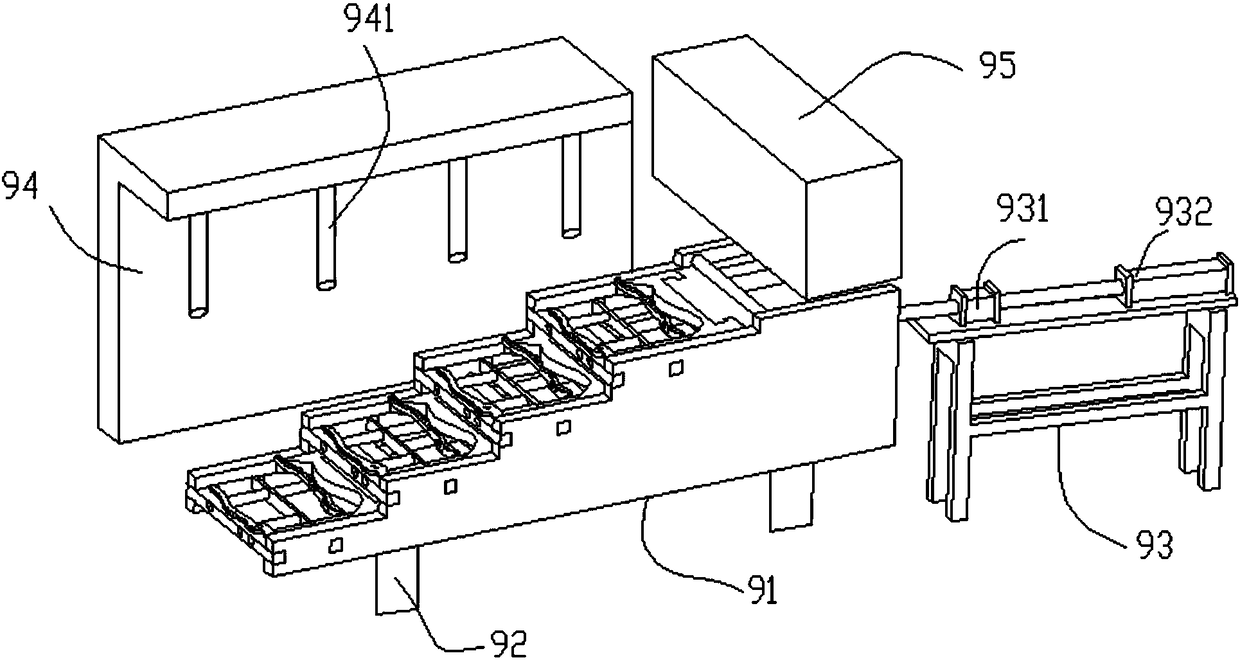
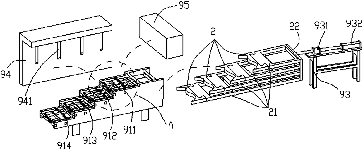
[0051] Such as Figure 1-Figure 8 As shown, the specific structure of the present invention is: a continuous drilling and milling machine tool for automatic blanking of anti-clogging pliers body, which includes an automatic feeding device 95 for feeding, and a processing warehouse 91 connected to the end of the automatic feeding device 95, The horizontal side of the processing chamber 91 is cooperatingly provided with a pusher assembly.

[0052] A processing base 92 is arranged below the processing chamber 91, and the processing chamber 91 is stacked in a step-like manner from top to bottom by a plura...


PUM


Abstract

The invention discloses an anti-blocking automatic forceps body blanking continuous drilling and milling machine tool which comprises an automatic feeding device for feeding, and a machining bin connected with the tail end of the automatic feeding device, wherein a push component is arranged on the horizontal side face of the machining bin in a matched manner; a machining base is arranged below the machining bin; the machining bin is formed by a plurality of machining layers that are sequentially stacked in a stepped manner; the machining layers are provided with forceps body guide rail sets;drilling machines for machining are arranged above the machining bin and correspond to the machining layers respectively; and the drilling machines are mounted on drilling machine bases arranged on the side edges. The anti-blocking automatic forceps body blanking continuous drilling and milling machine tool facilitates automatic sequential machining of forceps bodies, reduces misoperation possiblycaused in a forceps dropping process, avoids push plate blocking caused by machining scraps, improves machining and production efficiency, facilitates the automatic machining, increases a speed, improves an effect, and lowers machining cost.

Description

technical field [0001] The invention belongs to the field of hardware tool manufacturing, and relates to pliers processing equipment, in particular to an anti-blocking pliers body automatic blanking continuous drilling and milling processing machine tool. Background technique [0002] Pliers are a hardware tool that is widely used, and the head part of the pliers is the main working element of the pliers, which is used to cut electric wires, iron wires or thin iron sheets. The functional area of ​​the pliers head generally includes the following elements: inner cutting edge, outer cutting edge, square mouth, grinding disc, such as Figure 9-Figure 10 As shown, the pliers body 80 is composed of two symmetrical halves of the left and right centers, which respectively include a pliers head 81 and a pliers handle 82; on the pliers head 81, an outer cutting edge 802, an inner cutting edge 803 and Square opening 804, and grinding disc 801 for assembly. [0003] In the existing pl...

Claims


Application Information

Patent Timeline
IPC IPC(8): B23P23/02B23Q7/06
CPCB23P23/02B23Q7/06
Inventor 王再德陈龙王胜得王恒王琼
Owner SHAODONG HEXIE HARDWARE ELECTROMECHANICAL CO LTD
Why Eureka
Try Eureka