
Numerically-controlled vertical drilling device

A drilling device, digitally controlled vertical technology, applied in the field of numerically controlled vertical drilling devices, can solve the problems of cumbersome operation, low efficiency, lack of waste collection, etc., and achieve the effect of improving accuracy and efficiency and strengthening strength

Inactive Publication Date: 2018-07-24
周德明
View PDF4 Cites 2 Cited by
  • Summary
  • Abstract
  • Description
  • Claims
  • Application Information

AI Technical Summary

Problems solved by technology

[0003] At present, most CNC drilling machines can only drill a single hole on a fixed workpiece. The operation of continuous drilling is cumbersome and inefficient, and there is no collection of waste generated by drilling machines.

Method used


Image

  • Numerically-controlled vertical drilling device
  • Numerically-controlled vertical drilling device
  • Numerically-controlled vertical drilling device

Examples


Embodiment 1

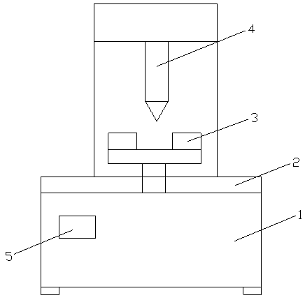
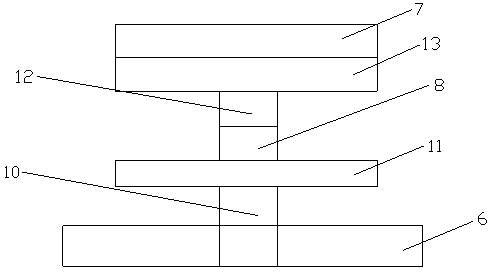
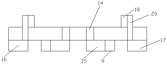
[0043] like Figure 1-6 As shown, a numerical control vertical drilling device includes a mechanical support 1, a positioning mechanism 2, a clamping mechanism 3, a drilling mechanism 4 and a control device 5, and the positioning mechanism 2, the drilling mechanism 4 and the control device 5 are all Installed on the mechanical support 1, the positioning mechanism 2 includes an electric guide rail 6, a rotating disk 7, a rotating motor 8 and a negative pressure fan 9, and the slider of the electric guide rail 6 is provided with a connecting rod 10, and the connecting rod 10 A fixed disk 11 is arranged on the fixed disk 11, and a rotary motor 8 is installed on the fixed disk 11. A speed reducer 12 is arranged on the transmission shaft of the rotary motor 8, and a speed reducer 13 is arranged on the output shaft of the speed reducer 12. A rotary disc 7 is installed on the deceleration disc 13, and the rotary disc 7 is provided with a waste material hole 14, and more than one wast...

Embodiment 2

[0051] like Figure 1-6 As shown, a numerical control vertical drilling device includes a mechanical support 1, a positioning mechanism 2, a clamping mechanism 3, a drilling mechanism 4 and a control device 5, and the positioning mechanism 2, the drilling mechanism 4 and the control device 5 are all Installed on the mechanical support 1, the positioning mechanism 2 includes an electric guide rail 6, a rotating disk 7, a rotating motor 8 and a negative pressure fan 9, and the slider of the electric guide rail 6 is provided with a connecting rod 10, and the connecting rod 10 A fixed disk 11 is arranged on the fixed disk 11, and a rotary motor 8 is installed on the fixed disk 11. A speed reducer 12 is arranged on the transmission shaft of the rotary motor 8, and a speed reducer 13 is arranged on the output shaft of the speed reducer 12. A rotary disc 7 is installed on the deceleration disc 13, and the rotary disc 7 is provided with a waste material hole 14, and more than one wast...


PUM


Abstract

The invention discloses a numerically-controlled vertical drilling device. The numerically-controlled vertical drilling device comprises a mechanical support, a positioning mechanism, clamping mechanisms, a drilling mechanism and a control device, wherein the positioning mechanism, the drilling mechanism and the control device are installed on the mechanical support; the positioning mechanism comprises an electric guide rail, a rotary plate, a rotary motor and negative-pressure fans; a slide block of the electric guide rail is provided with a connecting rod; a fixed plate is arranged on the connecting rod and provided with the rotary motor; a drive shaft of the rotary motor is provided with a speed reducer; an output shaft of the speed reducer is provided with a speed reduction plate; therotary plate is installed on the speed reduction plate and provided with one or more waste holes; waste bins are arranged on the waste holes, and the negative pressure fan are installed in the waste bins; and the clamping mechanisms are located on the rotary plate. The numerically-controlled vertical drilling device is accurate in positioning, compact in structure and high in efficiency and cleanness.

Description

technical field [0001] The invention relates to a numerical control vertical drilling device. Background technique [0002] CNC drilling machines are mainly used for drilling, reaming, reaming, tapping and other processing. In the automobile, locomotive, shipbuilding, aerospace, engineering machinery industries; especially for the drilling of various large-scale parts such as ultra-long stacked plates, longitudinal beams, structural steel, and tubular parts, it is the first choice. The vertical drilling machine is a vertically arranged drilling machine with a fixed center position, referred to as a vertical drill. Before machining on the vertical drilling machine, the position of the workpiece on the workbench must be adjusted so that the centerline of the machined hole is aligned with the axis of the tool. During processing, the workpiece is fixed, and the spindle rotates in the sleeve and feeds axially with the sleeve. The worktable and headstock can be adjusted along t...

Claims


Application Information

Patent Timeline
IPC IPC(8): B23B39/00B23Q3/06B23Q11/00C08L61/16C08L45/00C08L27/06C08K13/04C08K7/06C08K5/098C08K5/57C08K7/28C08K5/20C08K5/526
CPCB23B39/00B23Q3/06B23Q11/0046C08K2201/011C08K2201/014C08L61/16C08L2205/03C08L45/00C08L27/06C08K13/04C08K7/06C08K5/098C08K5/57C08K7/28C08K5/20C08K5/526
Inventor 周德明
Owner 周德明
Learn More