Continuous water supply device, water drinking system and industrial Hu sheep breeding equipment
A technology of water supply device and water outlet pipe, applied in the direction of animal drinking water device, application, animal husbandry, etc., can solve the problem of inability to supply water to lake sheep, and achieve the effects of simple structure, easy reading and easy manufacturing.
- Summary
- Abstract
- Description
- Claims
- Application Information
AI Technical Summary
Problems solved by technology
Method used
Image
Examples
Embodiment 1
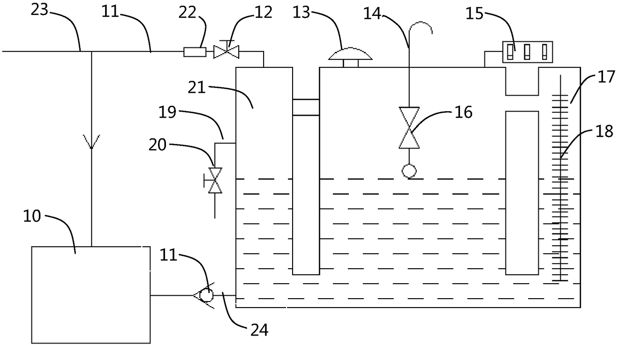
[0037] like figure 1 As shown, the continuous water supply device of this embodiment includes a water injection tank 21 and a ventilation mechanism. The top of the water injection tank 21 is provided with a water inlet pipe 23, and the bottom is provided with a water outlet pipe 24, wherein the water outlet pipe 24 is connected to the drinking fountain 10; the ventilation mechanism includes a ventilation bend Pipe 14 and float sealing valve 16, the lower end of the ventilation elbow 14 extends into the water injection tank 21, the float sealing valve 16 floats on the drinking water surface and leans against the lower end of the ventilation elbow 14, when the water inlet pipe 23 is normally supplied with water , the water injection tank 21 will continuously inject water, and the float seal valve 16 closes the vent elbow 14 to reduce the static pressure. Disconnect, the water injection tank 21 is connected and communicated with the atmosphere by the ventilation elbow 14, increas...
Embodiment 2
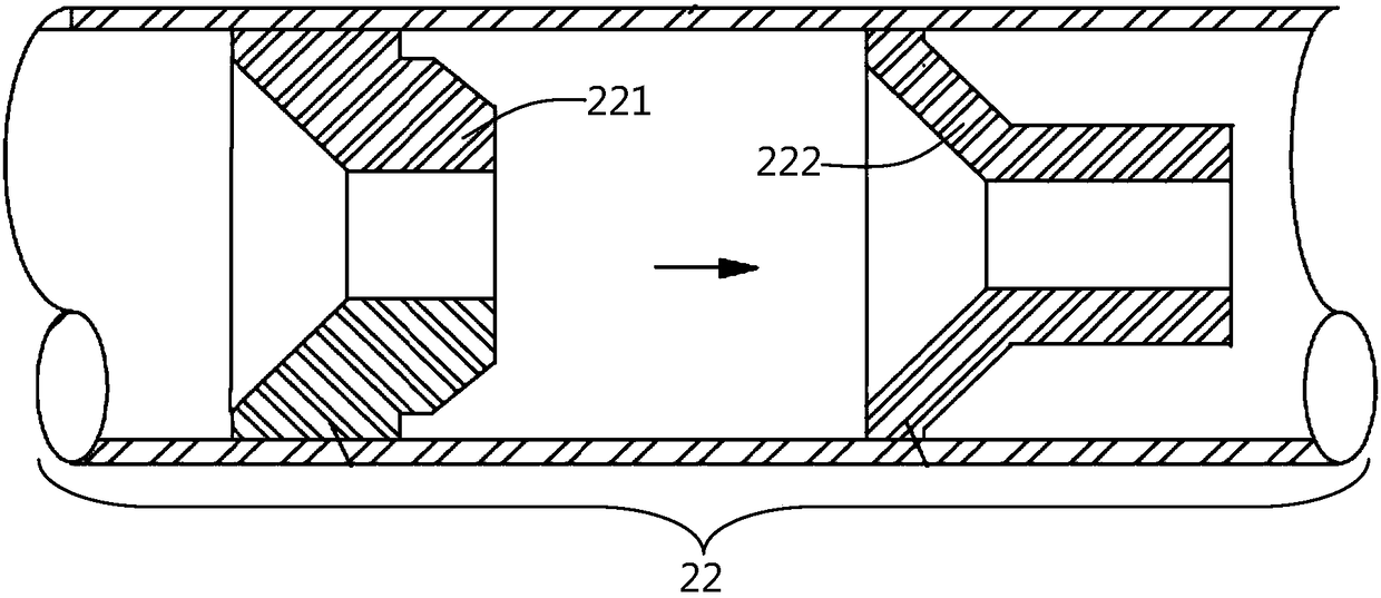
[0043] see figure 2 , the continuous water supply device of the present embodiment includes a water injection tank 21 and a ventilation mechanism, the top of the water injection tank 21 is provided with a water inlet pipe 23, and the bottom is provided with a water outlet pipe 24, wherein the water outlet pipe 24 is connected to the drinking fountain 10; the ventilation mechanism includes a ventilation elbow 14 And the float sealing valve 16, the lower end of the ventilation elbow 14 extends into the water injection tank 21, the float sealing valve 16 floats on the drinking water surface and leans against the lower end of the ventilation elbow 14, and a flow limiter 22 is arranged in front of the water inlet valve 12 .
[0044] Further, a restrictor 22 is provided in front of the water inlet valve 12 . like image 3 As shown, the restrictor 22 includes a first restrictor plate 221 and a second restrictor plate 222, the outer diameters of the first restrictor plate 221 and t...
Embodiment 3
[0046] Several of this embodiment are basically the same as Embodiment 2, the difference is that, as figure 1 , figure 2 As shown, one side of the water injection tank 21 is provided with an overflow pipe 19, and the mouth of the overflow pipe 19 is slightly higher than the upper limit water level line. high.
[0047] When the amount of water in the water injection tank 21 was too large (exceeding the set upper limit), then the water can be discharged outwards to ensure that the water pressure in the water injection tank 21 is consistent with the water pressure in the drinking fountain 10.
PUM
 Abstract
Description
Claims
Application Information
 - R&D
- Intellectual Property
- Life Sciences
- Materials
- Tech Scout
- Unparalleled Data Quality
- Higher Quality Content
- 60% Fewer Hallucinations
Browse by: Latest US Patents, China's latest patents, Technical Efficacy Thesaurus, Application Domain, Technology Topic, Popular Technical Reports.
© 2025 PatSnap. All rights reserved.Legal|Privacy policy|Modern Slavery Act Transparency Statement|Sitemap|About US| Contact US: help@patsnap.com


