
PCVD (plasma chemical vapor deposition) device

A deposition device and heating furnace technology, applied in the deposition device field of plasma chemical vapor deposition method, can solve the problems of increasing the cost of optical fiber, complex equipment structure, and the influence of the effective rod length of the preform, so as to reduce the standing wave intensity and improve the axis Uniformity and the effect of improving axial uniformity

Inactive Publication Date: 2018-07-20
YANGTZE OPTICAL FIBRE & CABLE CO LTD
View PDF6 Cites 0 Cited by
  • Summary
  • Abstract
  • Description
  • Claims
  • Application Information

AI Technical Summary

Problems solved by technology

The results show that this method improves the axial uniformity of the preform, but when the deposition rate increases or the feed power increases, it will affect the effective rod length of the preform, which will increase the cost of the optical fiber
Moreover, the equipment structure of this method is relatively complicated.

Method used


Image

  • PCVD (plasma chemical vapor deposition) device
  • PCVD (plasma chemical vapor deposition) device
  • PCVD (plasma chemical vapor deposition) device

Examples


Embodiment Construction

[0024] The present invention will be described in further detail below in conjunction with the accompanying drawings.

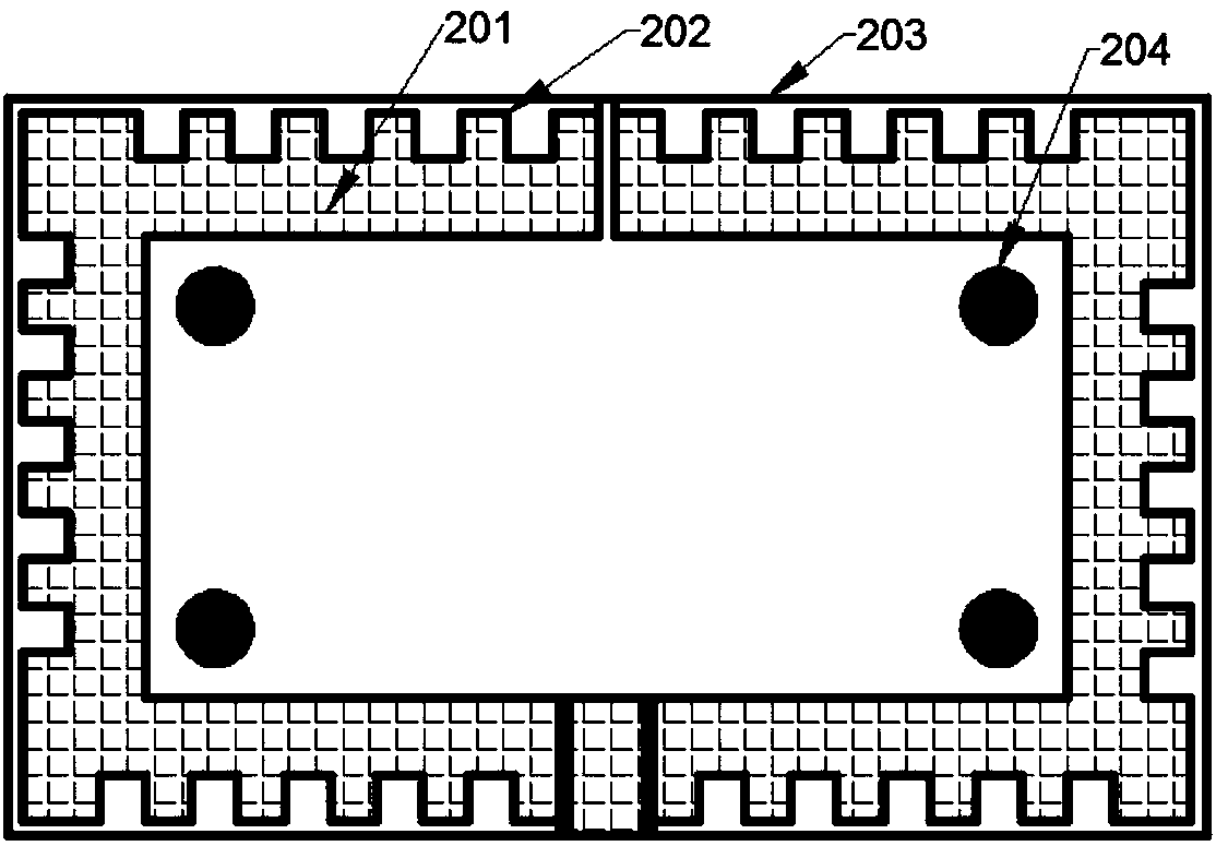
[0025] The first embodiment into figure 1 , 3 As shown, it includes a long cylindrical heating furnace and a resonant cavity 102 installed in the furnace cavity of the heating furnace. The long cylindrical heating furnace is composed of a furnace body that is opened and closed in half, and an open channel for the reciprocating operation of the resonant cavity is arranged in the middle of the lower end. The above-mentioned resonant cavity extends out of the heating furnace through the waveguide through the opening channel, and is connected with the axial reciprocating device and the microwave source 105, and is connected with the impedance matching unit 104. The glass liner 103 is installed along the axial direction of the heating furnace and passes through the resonant cavity. The reciprocating device drives the resonant cavity to reciprocate in the heating ...


PUM


Abstract

The invention relates to a PCVD (plasma chemical vapor deposition) device, which comprises a long tubular heating furnace and a resonant cavity arranged in a furnace cavity of the heating furnace, wherein the resonant cavity extends out of the heating furnace through wave guide and is connected with an axial reciprocating device and a microwave source; the long tubular heating furnace comprises acasing; a heat insulation layer is arranged on the inner wall of the casing; a heating element is arranged in a furnace cavity of the heating furnace in the circumferential direction. The PCVD deviceis characterized in that a wave absorption layer is laid between the heating furnace casing and the heat insulation layer; the wave absorption layer is formed by convex blocks with the same shape through uniform arrangement. The microwaves leaked into the furnace cavity of the heating furnace can be absorbed after the multi-time reflection and refraction; the goals of reducing the intensity of standing waves in the heating furnace is achieved, so that the axial uniformity of the deposition is improved; the parameter of a core rod of an optical fiber prefabricated rod is improved. The influenceof the standing waves in the furnace on the optical fiber parameter is reduced, so that the microwave intensity leaked into a workshop can be correspondingly reduced; the harm to the bodies of operation personnel in the workshop is reduced. The axial uniformity of the core rod is improved, so that the length of the qualified core rod is increased; the optical fiber manufacturing cost is reduced.

Description

technical field [0001] The invention relates to a deposition device for plasma chemical vapor deposition method used to deposit and manufacture optical fiber preform rods, that is, a PCVD deposition device, and belongs to the technical field of optical fiber preform rod processing equipment. Background technique [0002] Optical fiber communication technology has become an extremely important pillar of modern communication. In recent years, with the development of the Internet and the increasing demand for network bandwidth, the demand for optical fibers has increased rapidly. It is urgent to increase the production rate of optical fiber manufacturing, reduce the cost of optical fiber production, and improve the processing quality of optical fibers. In the process of preparing the optical fiber preform by PCVD deposition, the microwave source is used as the magnetron, and the center frequency is 2.45GHz or 915MHz. The glass liner is inserted into the metal resonant cavity, ...

Claims


Application Information

Patent Timeline
IPC IPC(8): C03B37/018
CPCC03B37/018
Inventor 胡肖张欣朱继红汪洪海
Owner YANGTZE OPTICAL FIBRE & CABLE CO LTD
Learn More