Circuit and method for MOS tube self inspection of three-phase brushless direct current motor
A brushless DC motor and MOS tube technology, applied in the direction of measuring electricity, measuring electrical variables, measuring devices, etc., can solve the problems of low safety and time-consuming detection, and achieve the effects of improved safety performance, low cost, and avoiding damage
- Summary
- Abstract
- Description
- Claims
- Application Information
AI Technical Summary
Problems solved by technology
Method used
Image
Examples
Embodiment A
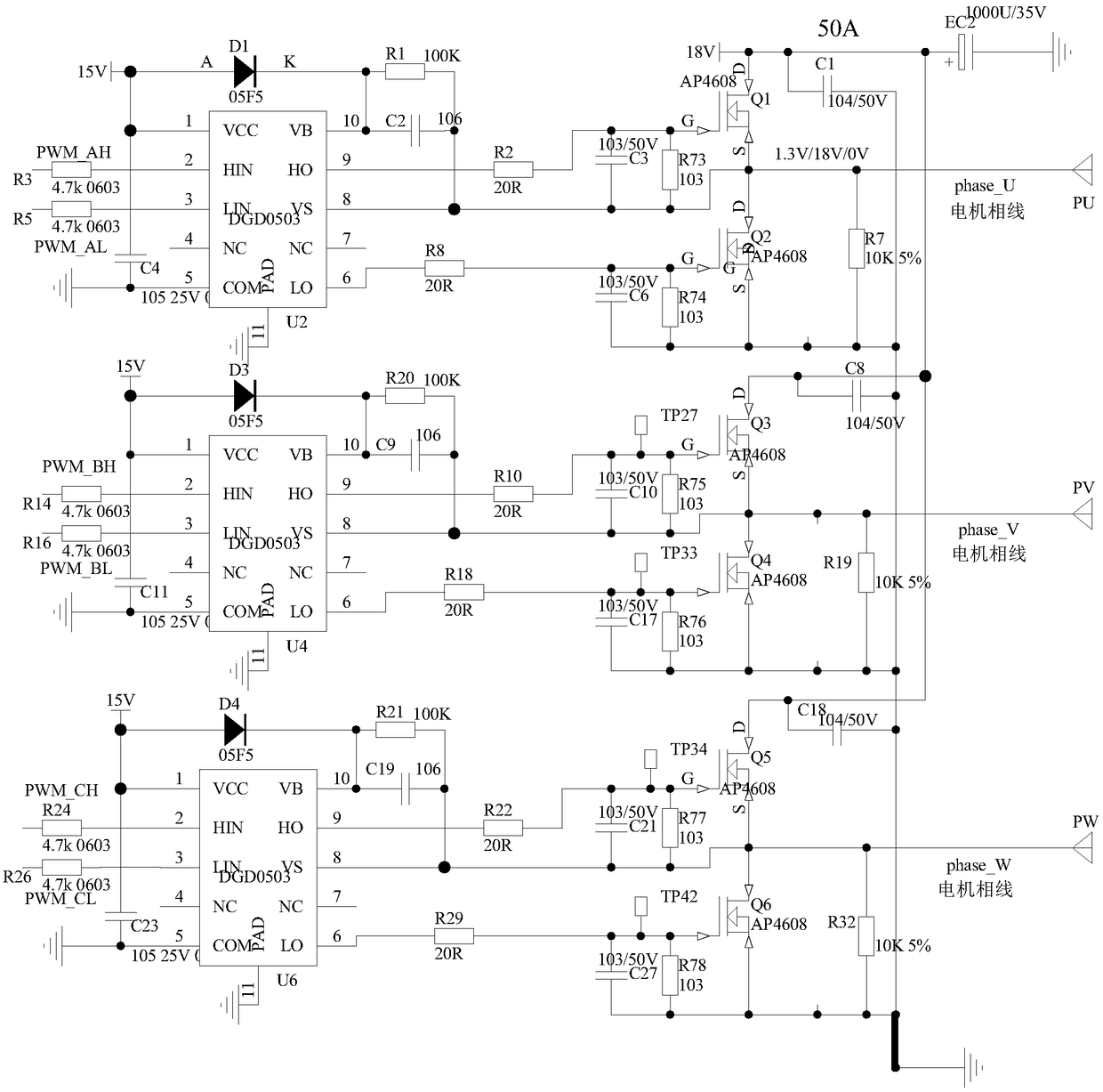
[0051] How to judge whether the MOS transistors Q1, Q3, and Q5 are short-circuited is described in detail below.
[0052] In the embodiment of the present invention, in a specific implementation of the reference voltage unit, the MCU as the control unit respectively makes the output terminal volt_ceter of the reference voltage unit output the reference voltage through the resistors R4 and R6 on the reference voltage unit, specifically The implementation is as follows:
[0053] The MCU program controls the I / O pin connected to the resistor R4, and connects the resistor R4 to the pull-up resistor inside the MCU; the MCU program controls the I / O pin connected to the resistor R6, connects the resistor R6 to GND, and the resistor R4, The other end of R6 is a common terminal, and is connected to the output terminal volt_ceter of the reference voltage unit, so that the output terminal volt_ceter of the reference voltage unit forms a reference voltage, for example, the reference volta...
Embodiment B
[0061] How to determine whether the MOS transistors Q2, Q4, and Q6 are short-circuited will be described in detail below.
[0062] In the embodiment of the present invention, the MCU uses the resistors R4 and R6 on the reference voltage unit to make the volt_ceter output the reference voltage, and the way to detect whether Q2 is short-circuited is as follows:
[0063] The MCU program controls the I / O pin connected to the resistor R4, and connects the resistor R4 to GND; the MCU program controls the I / O pin connected to the resistor R6, and connects the resistor R6 to the pull-up resistor inside the MCU; make the volt_ceter The voltage is about 0.095V (to simplify the analysis, 0.095V is only the voltage division result of resistor R4 and resistor R6, and other voltage division networks are ignored).
[0064] If both Q1 and Q2 MOS tubes are good, then the voltage at the phase line phase_U is about 1.3V after 15V is divided by the bootstrap diode D1, the voltage dividing resisto...
Embodiment C
[0075] The following details how to detect whether Q1, Q3, and Q5 are open.
[0076] In the embodiment of the present invention, if a short circuit is detected after the MOS tube short circuit detection process is completed, an error prompt will be issued, indicating that there is a problem with the circuit, and the open circuit detection will not be performed further down. If no short circuit is detected, the MOS tube will be further detected. Whether the tube is open.
[0077] Here we still take Q1 as an example, and the details are as follows:
[0078] In a specific implementation of the reference voltage unit, the MCU makes the output terminal volt_ceter of the reference voltage unit output the reference voltage through the resistors R4 and R6 on the reference voltage unit respectively.
[0079] The MCU makes the volt_ceter output the reference voltage through the resistor R4 and the resistor R6. In detail, the MCU program controls the I / O pin connected to the resistor R...
PUM
 Abstract
Description
Claims
Application Information
 - R&D
- Intellectual Property
- Life Sciences
- Materials
- Tech Scout
- Unparalleled Data Quality
- Higher Quality Content
- 60% Fewer Hallucinations
Browse by: Latest US Patents, China's latest patents, Technical Efficacy Thesaurus, Application Domain, Technology Topic, Popular Technical Reports.
© 2025 PatSnap. All rights reserved.Legal|Privacy policy|Modern Slavery Act Transparency Statement|Sitemap|About US| Contact US: help@patsnap.com


