Anti-lateral-collision bearing with ball oil storage mechanism

A ball, anti-side technology, applied in the direction of rolling contact bearings, rotating bearings, bearings, etc., can solve the problems of deformation of rolling groove or ball 3, increased resistance, separation, etc., to reduce friction, avoid contact, improve The effect of impact resistance

Inactive Publication Date: 2018-07-13
郑帆
View PDF1 Cites 6 Cited by
  • Summary
  • Abstract
  • Description
  • Claims
  • Application Information

AI Technical Summary

Problems solved by technology

[0005] 1. The anti-shock structure is set on one side, that is, the bearing can only prevent side impact force on one side, and the opposite direction will still cause the entire bearing inner ring 2 and bearing outer ring 1 to separate
[0006] 2. When hitting the base 5, the inner ring 2 will be slightly dislocated relative to the outer ring 1, causing the inner ball 3 to be sandwiched between the inner ring 2 and the outer ring 1, and the ball 3 will be clamped inside. Failure to reset in time will easily lead to deformation of the rolling groove or ball 3
[0007] 3. The buffer ball 6 keeps in contact with the side wall of the outer ring, and the friction makes the resistance increase

Method used


Image

  • Anti-lateral-collision bearing with ball oil storage mechanism
  • Anti-lateral-collision bearing with ball oil storage mechanism
  • Anti-lateral-collision bearing with ball oil storage mechanism

Examples


Embodiment 1

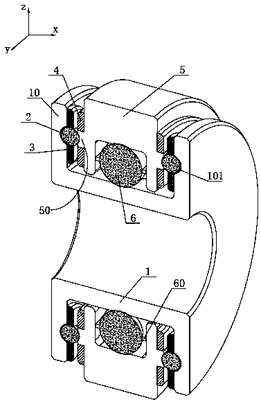
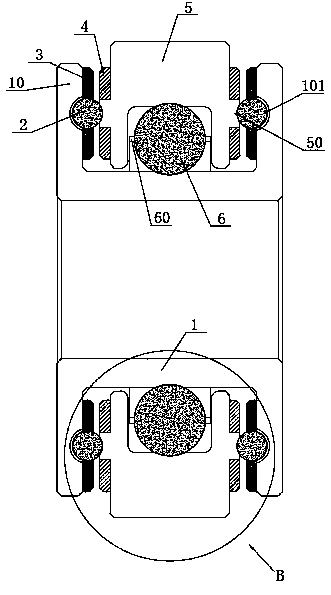
[0044] Such as Figure 11The anti-side impact bearing with ball oil storage mechanism shown includes inner ball 6, outer ring 5, inner magnetic ring 4, outer magnetic block 3, outer ball 2 and inner ring 1 from the inside to both sides (for better convenience) See the positional relationship, the outer ring 5 and the inner ring 1 are all cut from the middle in the figure).

[0045] A cage 60 is provided on the outside of the inner ball 6 for maintaining the distance between the balls.

[0046] The outermost side is the impact wall 10 of the inner ring 1, the impact wall 10 is parallel to the side wall of the outer ring 5, the impact wall 10 is parallel to the rotation surface of the inner ring 1, and the gap between the impact wall 10 and the side wall of the outer ring 5 An anti-collision mechanism is provided, and the anti-collision mechanism includes a socket 100, an outer rolling groove, an outer ball 2 and an outer magnetic block 3 for fixing the outer ball 2; the outer ...

Embodiment 2

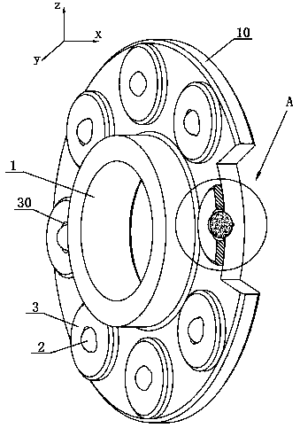
[0059] Such as Figure 6 As shown, this embodiment is based on Embodiment 1, and integrates all the outer magnetic blocks 3 into a whole. The outer magnetic block 3 in this embodiment is annular, and the outer magnetic block 3 surrounds the inner ring 1 and is connected to the inner ring Circle 1 is set concentrically.

[0060] The outer magnetic block 3 is a structure of a whole magnetic ring. There are multiple holes on the magnetic ring for the outer ball 2 to be exposed. The advantage is that it is easy to install and can provide greater magnetic repulsion. However, when assembling and disassembling, it needs Overall disassembly.


PUM


Abstract

An anti-lateral-collision bearing with a ball oil storage mechanism is disclosed. The anti-lateral-collision bearing is provided with a collision-resistant mechanism, the collision-resistant mechanismcomprises an embedment groove, an outer roll groove, an outer ball, an outer magnetic block for fixing of the outer ball, and an inner magnet with a magnet pole being repellant with that of an outermagnet. The outer ball is embedded between the embedment groove and the outer magnetic block. A hole for enabling the outer ball to be exposed is formed in the outer magnetic block, inner magnetic rings are located on the two sides of the outer roll groove, and the outer ball is made of a non-magnetic attraction material. The collision-resistant mechanism rolls on the outer roll groove through theball and can counteract most axial collision force. Repulsive force exists between an inner magnetic block and the outer magnetic block and enables a certain gap to exist between the ball and the outer roll groove, and abrasion caused by friction is reduced. The ball oil storage mechanism is further arranged, two oil passing holes are formed in the ball oil storage mechanism, lubricating oil brought out through rolling of the ball can be stored temporarily, the brought-out lubricating oil is prevented from being stacked on the interface, particles such as dust falling into the bearing are stored temporarily, deformation and abrasion are avoided, and the service life of the bearing is prolonged.

Description

technical field [0001] The invention relates to a bearing, in particular to an anti-side impact bearing with a ball oil storage mechanism. Background technique [0002] Common bearings in the market generally have the same problem, that is, the bearing cannot bear the axial pressure. When the axial load exceeds the bearing capacity of the bearing, the bearing will collapse, posing serious safety hazards and easily causing major accidents. [0003] At present, the Chinese patent No. 201420441003.4 discloses a stainless steel bearing that can withstand axial impact force. The impact-resistant structure includes a buffer ball and a circular groove, the circular groove is located on the upper end surface, the buffer ball fits with the circular groove, and 1 / 2 to 1 / 4 of the volume of the buffer ball is placed outside the circular groove. Buffer balls and circular grooves are used to withstand axial impact, reduce friction caused by axial loads, and prevent bearings from suddenly...

Claims


Application Information

Patent Timeline
Patent Type & Authority Applications(China)
IPC IPC(8): F16C19/50F16C19/52F16C33/66
CPCF16C19/505F16C19/522F16C33/6681
Inventor 郑帆
Owner 郑帆
Why Eureka
Try Eureka