Thermomagnetic device for spray molding of decorative balls

A decorative ball and plastic spraying technology, which is applied in the direction of spraying devices, electrostatic spraying devices, spray booths, etc., can solve the problem that the thickness of the paint layer on the surface of the magnetic decorative ball is difficult to ensure uniformity, the thickness of the surface paint layer is difficult to ensure uniformity, and the consumption of plastic powder is large. And other problems, to achieve the effect of easy to ensure uniform thickness of surface paint layer, wide range of weight, and small consumption of plastic powder

Inactive Publication Date: 2018-07-10
湖州正鸣塑胶科技有限公司
View PDF0 Cites 0 Cited by
  • Summary
  • Abstract
  • Description
  • Claims
  • Application Information

AI Technical Summary

Problems solved by technology

When the existing magnetic decorative ball is sprayed, it is carried out in a large space, only a small part of the plastic powder is sprayed on the surface of the magnetic decorative ball, most of the plastic powder is wasted, and the consumption of plastic powder large
The angle and time of powder spraying are manually controlled by the existing magnetic decorative balls during plastic spraying. It is difficult to spray the plastic powder evenly on the surface of the magnetic decorative balls, and it is difficult to ensure uniform thickness of the paint layer on the surface of the magnetic decorative balls.
Therefore, the existing magnetic decorative balls have the defects of low aesthetic feeling, large consumption of plastic powder and difficulty in ensuring uniform thickness of the surface paint layer.

Method used


Image

  • Thermomagnetic device for spray molding of decorative balls

Examples


Embodiment Construction

[0013] The present invention will be further described below in conjunction with the accompanying drawings and embodiments, but not as a basis for limiting the present invention.

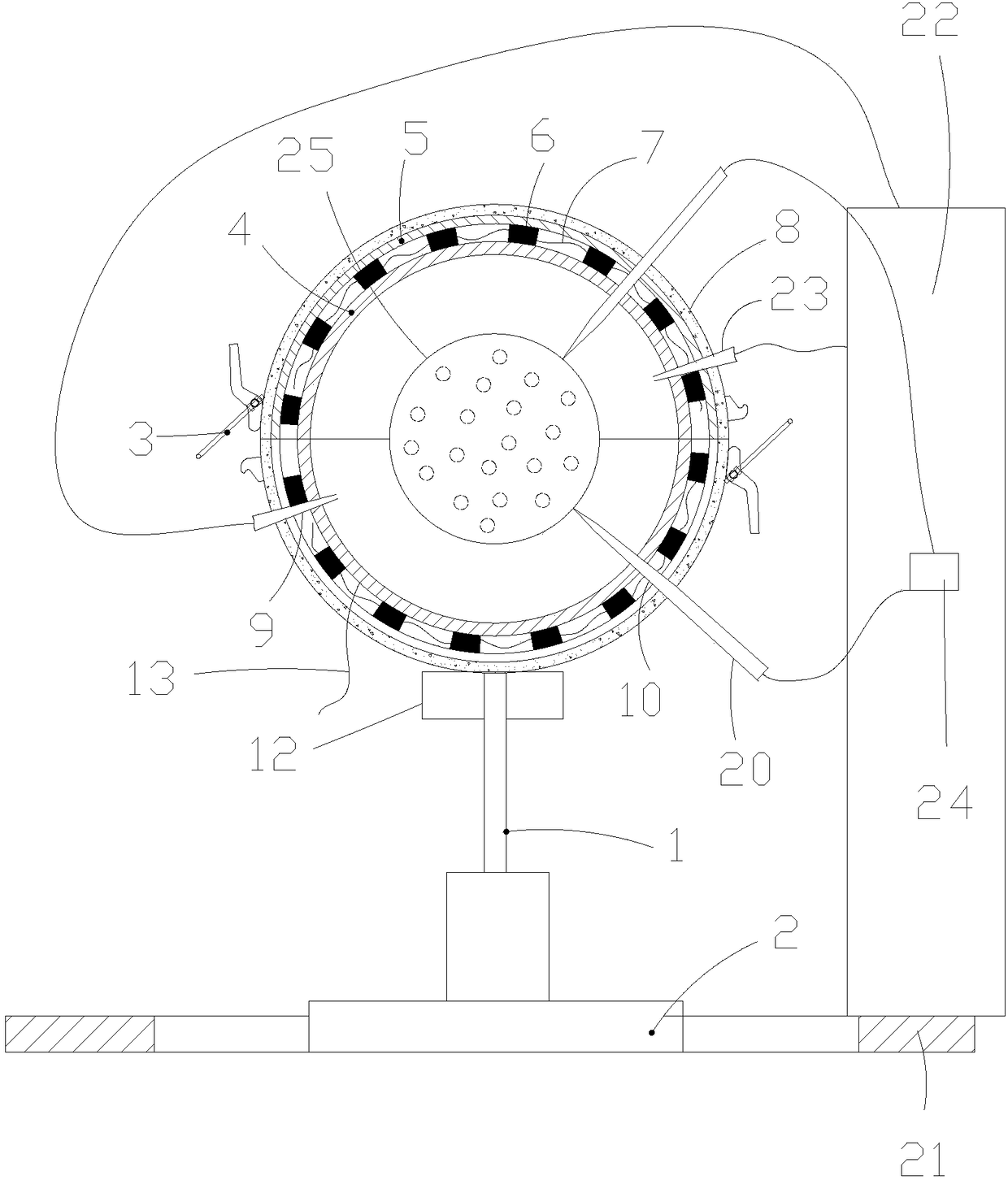
[0014] Example. A thermal-magnetic device for spraying decorative balls, comprising a hollow sphere, a bottom plate 2 is arranged below the hollow sphere, a motor 1 is arranged on the bottom plate 2, the output shaft of the motor 1 is connected with the hollow sphere, and the hollow sphere is composed of upper and lower hemispheres The two shells are connected by a quick lock 3. The shell includes an inner shell 4 and an outer shell 5. A plurality of evenly distributed magnets 6 are arranged between the inner shell 4 and the outer shell 5. , a heating wire 7 is provided between the inner shell 4 and the outer shell 5, the outer shell 5 is covered with an insulation layer 8, the shell is provided with a spray gun hole 9 and a conductive hole 10, and a needle bar 20 is arranged in the conductive hole ...


PUM


Abstract

The invention discloses a thermomagnetic device for spray molding of decorative balls. The thermomagnetic device comprises a hollow sphere; a bottom plate is arranged under the hollow sphere and is provided with a motor; an output shaft of the motor is connected with the hollow sphere; the hollow sphere consists of two hemispherical shells which are respectively arranged at the upper part and thelower part; the two shells are connected with each other by means of a rapid lock catch; each shell comprises an inner shell and an outer shell, wherein a plurality of evenly distributed magnets are arranged between the inner shell and the outer shell; electric heating wires are arranged between the inner shells and the outer shells; an insulating thermal insulation layer covers each outer shell;each shell is provided with a spray gun hole and a conductive hole; each conductive hole is internally provided with a needle bar; a ring-shaped conveyor belt is arranged at the outer ring of the motor; the conveyor belt is provided with an electrostatic spray molding machine; spray guns on the electrostatic spray molding machine are arranged in the spray gun holes; an electrode on the electrostatic spray molding machine is connected with the needle bars. The thermomagnetic device for the spray molding of the decorative balls has the advantages of being high in aesthetic feeling degree, low inmolding powder consumption and easy in uniformity guarantee of surface paintcoat thickness.

Description

technical field [0001] The invention belongs to the field of movable decorative balls for hotels, in particular to a thermomagnetic device for plastic spraying of decorative balls. Background technique [0002] Decorative balls are generally set in the lobby or the living room of the guest room in the hotel. Their function is to embellish and match with the environment to create an atmosphere. The movable decorative ball is a kind of decorative ball. Compared with the fixed decorative ball, the movable decorative ball is not fixed with any object, but only placed on the tray or bracket. It has two advantages. One is It is convenient for the hotel to replace and use, and the second is that it can be picked up by customers. A magnetic decorative ball is a movable decorative ball with multiple magnets evenly distributed inside. There are multiple evenly distributed magnets inside, and the magnetic poles of the magnets are facing the same direction. The magnetic decorative ball...

Claims


Application Information

Patent Timeline
Patent Type & Authority Applications(China)
IPC IPC(8): B05B5/08B05B13/04B05B16/40B05B13/02
CPCB05B5/081B05B5/082B05B13/02B05B13/0421
Inventor 林峰
Owner 湖州正鸣塑胶科技有限公司
Why Eureka
Try Eureka