Frequency multiplication photoelectric oscillator

A photoelectric oscillator and frequency doubling technology, which is applied in photonic technology and microwave fields, can solve the problems of phase noise deterioration, high cost, and increase in output frequency doubling signal, and achieve the effect of strong practical prospects.

Inactive Publication Date: 2018-07-06
SOUTHEAST UNIV
View PDF4 Cites 0 Cited by
  • Summary
  • Abstract
  • Description
  • Claims
  • Application Information

AI Technical Summary

Problems solved by technology

Such a structure requires a large cost, and the risk of phase noise deterioration of the output frequency multiplied signal also increases with the increase in the use of active devices

Method used


Image

  • Frequency multiplication photoelectric oscillator
  • Frequency multiplication photoelectric oscillator

Examples


Embodiment Construction

[0019] The technical solutions of the present invention will be further described below in conjunction with the accompanying drawings and embodiments.

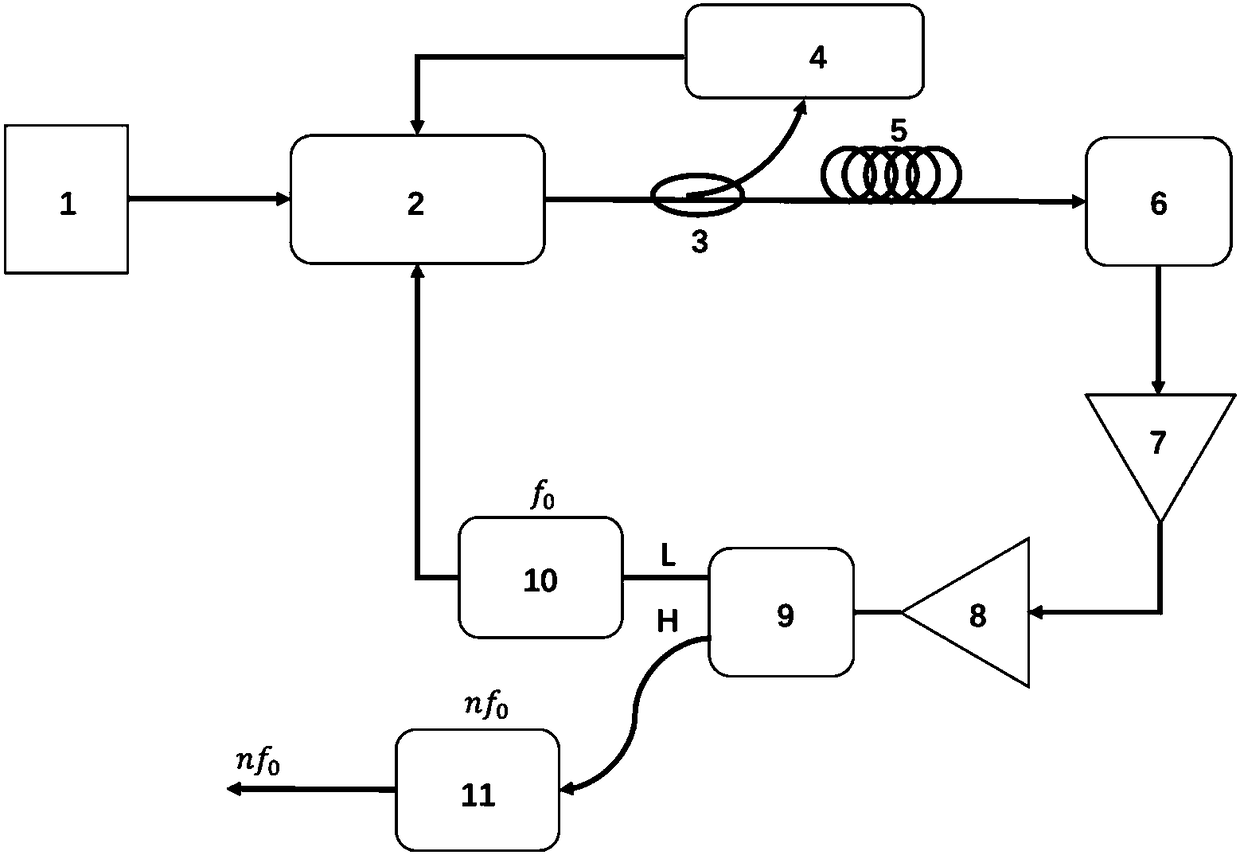
[0020] Such as figure 1 As shown, the frequency doubled photoelectric oscillator of the present invention includes a constant optical power output laser 1, an electro-optic modulator 2, an optical coupler 3, a bias control circuit 4, a long optical fiber 5, an optical detector 6, and a first stage Amplifier 7, second stage amplifier 8, duplexer 9, center frequency is f 0 A band-pass filter 10 with a center frequency of nf 0 The bandpass filter 11. In this article, nf 0 Both represent n times f 0 , n is an integer.

[0021] The laser 1 outputs a constant optical power, the output optical signal enters the electro-optic modulator 2, and the output terminal of the electro-optic modulator 2 is connected with an optical coupler 3 to realize light splitting. A part of the optical signal is sent to the bias control circuit 4, a...


PUM


Abstract

The invention discloses a frequency multiplication photoelectric oscillator. The laser output optical signal enters into an electro-optical modulator. The output of the electro-optic modulator is connected with the optical coupler to realize the light splitting. A part of the optical signal is sent to the bias control circuit. The working point of the electro-optical modulator is controlled; another portion of the optical signal enters into the photodetector via an optical fiber. The optical detector converts the optical signal to an electrical signal. The output end of the photodetector is connected with a two-stage series amplifier. The output of the series amplifier is connected with a duplexer. One port of the duplexer outputs a signal with frequency f0 and is output to a band-pass filter with the center frequency f0, and then is output to a drive signal port of the electro-optical modulator to form a loop with a frequency f0; the other output port of the duplexer outputs a signalwith a frequency of nf0, and is then output to a band-pass filter with a central frequency of nf0 to obtain an n-multiplied oscillation signal. The photoelectric oscillator fully utilizes the frequency multiplication characteristic of the electric amplifier in the photoelectric oscillator to operate in the saturation region, realizes the frequency multiplication of the oscillation signal by usingfewer devices and has strong practical prospect.

Description

technical field [0001] The invention relates to the fields of photon technology and microwave technology, in particular to a frequency-doubled photoelectric oscillator. Background technique [0002] Traditional high-performance microwave signal sources mostly use electric energy storage elements such as dielectric cavity oscillators, and acoustic energy storage elements such as quartz crystal oscillators to form resonant cavities. When the operating frequency of dielectric cavities and crystal resonators exceeds gigahertz, their quality factors drop rapidly, and the resulting microwave signals have poor phase noise. [0003] The photoelectric oscillator uses a long optical fiber with a loss of 0.2dB / km to realize a high-Q optical ring cavity and generate an oscillation signal with ultra-low phase noise, and the phase noise of the oscillation signal has the advantage of not deteriorating with the increase of the oscillation frequency. , military and other fields have broad a...

Claims


Application Information

Patent Timeline
Patent Type & Authority Applications(China)
IPC IPC(8): H01S1/02
CPCH01S1/02
Inventor 杨春徐玮杰王子晔吴建辉时龙兴
Owner SOUTHEAST UNIV
Why Eureka
Try Eureka