Filling machine buffer tank

A buffer tank and filling machine technology, applied in the field of medicine, can solve the problems that the fluctuation of the liquid level in the buffer tank has a great influence, affect the quality and efficiency of canning, and achieve the effect of increasing the cross-sectional area

Inactive Publication Date: 2018-07-06
JIANGSU PENGYAO PHARMA
View PDF6 Cites 0 Cited by
  • Summary
  • Abstract
  • Description
  • Claims
  • Application Information

AI Technical Summary

Problems solved by technology

Since the buffer tank is used to collect the mixed liquid, the buffer tank is also an ingredient collection device. Generally, the design structure of the buffer tank is designed with a cover plate with a through hole at the top, and the liquid inlet extends below the through hole. Such a design can effectively prevent the ingredient mixture from overflowing or splashing out of the buffer tank, but there is a distance between the liquid inlet and the bottom of the buffer tank, which will greatly affect the fluctuation of the liquid level in the buffer tank when feeding, which will affect the quality and efficiency of canning
In response to this situation, reducing the distance between the liquid inlet and the bottom of the buffer tank can reduce fluctuations in the liquid level, but the smaller the distance between the liquid inlet and the bottom of the buffer tank, the greater the vibration of the liquid at the bottom of the buffer tank, which will also affect the quality of the can and efficiency

Method used


Image

  • Filling machine buffer tank

Examples


Embodiment 1

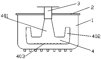
[0017] Such as figure 1 A filling machine buffer tank shown includes a tank body 1, the top of the tank body is provided with a cover plate 2 with a through hole, and a liquid inlet pipe nozzle 3 extends into the tank body through the through hole of the cover plate. The bottom of the nozzle 3 of the liquid pipe is connected to the mountain-shaped shunt pipe 4, which includes a connecting pipe 401 in the middle and liquid outlet pipes 402 located on both sides of the connecting pipe, and a number of micropores 403 are provided at the bottom.

Embodiment 2

[0019] With reference to Example 1, the height of the outlet pipe is higher than that of the connecting pipe, the connection between the horizontal pipe of the mountain-shaped shunt pipe and the longitudinal connecting pipe and the outlet pipe is an R angle with a radian, and the liquid inlet pipe The cross-sectional area of ​​the bottom of the nozzle ≤ the cross-sectional area of ​​the top of the connecting pipe ≤ the cross-sectional area of ​​the bottom of the connecting pipe.


PUM


Abstract

The invention discloses a filling machine buffer tank which comprises a tank body; a cover plate with a through hole is arranged at the top of the tank body; a liquid inlet pipe opening stretches intothe tank body through the through hole of the cover plate; and the bottom of the liquid inlet pipe opening is connected with an E-shaped manifold. Compared with the prior art, the E-shaped manifold is connected with a liquid inlet pipe, when the liquid level exceeds the heights of liquid outlet pipes, the liquid inlet mode of overflowing under the liquid level is achieved, and impact force on theliquid level during liquid feeding is reduced; the sectional area of a middle connecting pipe of the E-shaped manifold is greater than the sectional area of the liquid inlet pipe opening, so that theliquid inlet speed is reduced, and the influence on fluctuation of the liquid level is reduced as far as possible; the E-shaped manifold is provided with the two liquid outlet pipes, so that the sectional area of liquid outlet pipe openings is increased, and the liquid flow speeds of the liquid outlet pipe openings are reduced; and with the design of micropores in the bottom of the E-shaped manifold, accumulated liquid in the E-shaped manifold can be discharged completely, and no residual dead water is remained.

Description

technical field [0001] The invention belongs to the field of medicine, and in particular relates to a filling machine buffer tank. Background technique [0002] In modern society, medicine is closely related to human life, and filling machines for pharmaceutical liquids are very important in the preparation of medicines. The filling machine for medical liquids is mainly used for canning liquids such as oral liquids, injections, and disinfectants. At present, a buffer tank is usually added on the top of the filling machine during the use of the filling machine. The purpose of this buffer tank is to collect the mixed liquid after ingredients in the buffer tank first, and then enter the filling machine from the buffer tank for further processing. Canned into containers. Since the buffer tank is used to collect the mixed liquid, the buffer tank is also an ingredient collection device. Generally, the design structure of the buffer tank is designed with a cover plate with a thro...

Claims


Application Information

Patent Timeline
Patent Type & Authority Applications(China)
IPC IPC(8): B65B3/00B65B3/04
CPCB65B3/003B65B3/04
Inventor 周健夏良良梁小东杨杰吴洪君
Owner JIANGSU PENGYAO PHARMA
Why Eureka
Try Eureka