
Automatic edge removal machine for rubber product

A technology of rubber products and edge removal machines, which is applied in the direction of using gaseous coolants for modification, cooling/ventilation/heating modification, electrical components, etc., which can solve the problems of low heat dissipation efficiency of equipment, low working stability, and unfavorable equipment use. , to achieve the effect of convenient movement, guaranteed performance and high heat dissipation efficiency

Inactive Publication Date: 2018-07-06
海宁市晨丰橡塑有限公司
View PDF2 Cites 5 Cited by
  • Summary
  • Abstract
  • Description
  • Claims
  • Application Information

AI Technical Summary

Problems solved by technology

[0002] The rubber edge removal machine is a kind of aerodynamic principle, adopts the centrifugal principle, and there is an automatically controlled rotating disc in the cylinder to drive the rubber product to rotate at a high speed and continuously collide, so that the burrs and rubber products are separated from each other, so as to achieve the function of removing burrs , perfectly replaces the traditional manual, freezing and punching processes, and realizes the automatic edge removal machine for trimming and finishing rubber molded products. The existing automatic edge removal machine is large in size and inconvenient to move, and some equipment is equipped with pulleys. , the working stability is not high, and the heat dissipation efficiency of the equipment is low, which is not conducive to the use of the equipment

Method used


Image

  • Automatic edge removal machine for rubber product
  • Automatic edge removal machine for rubber product
  • Automatic edge removal machine for rubber product

Examples


Embodiment Construction

[0016] The preferred embodiments of the present invention will be described below in conjunction with the accompanying drawings. It should be understood that the preferred embodiments described here are only used to illustrate and explain the present invention, and are not intended to limit the present invention.

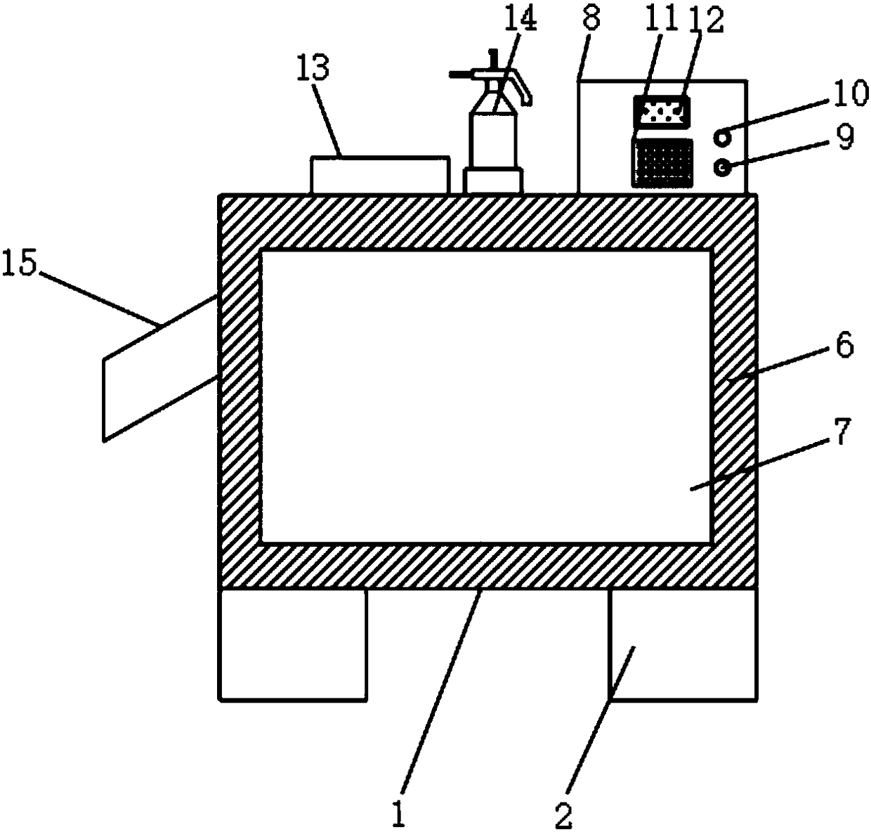
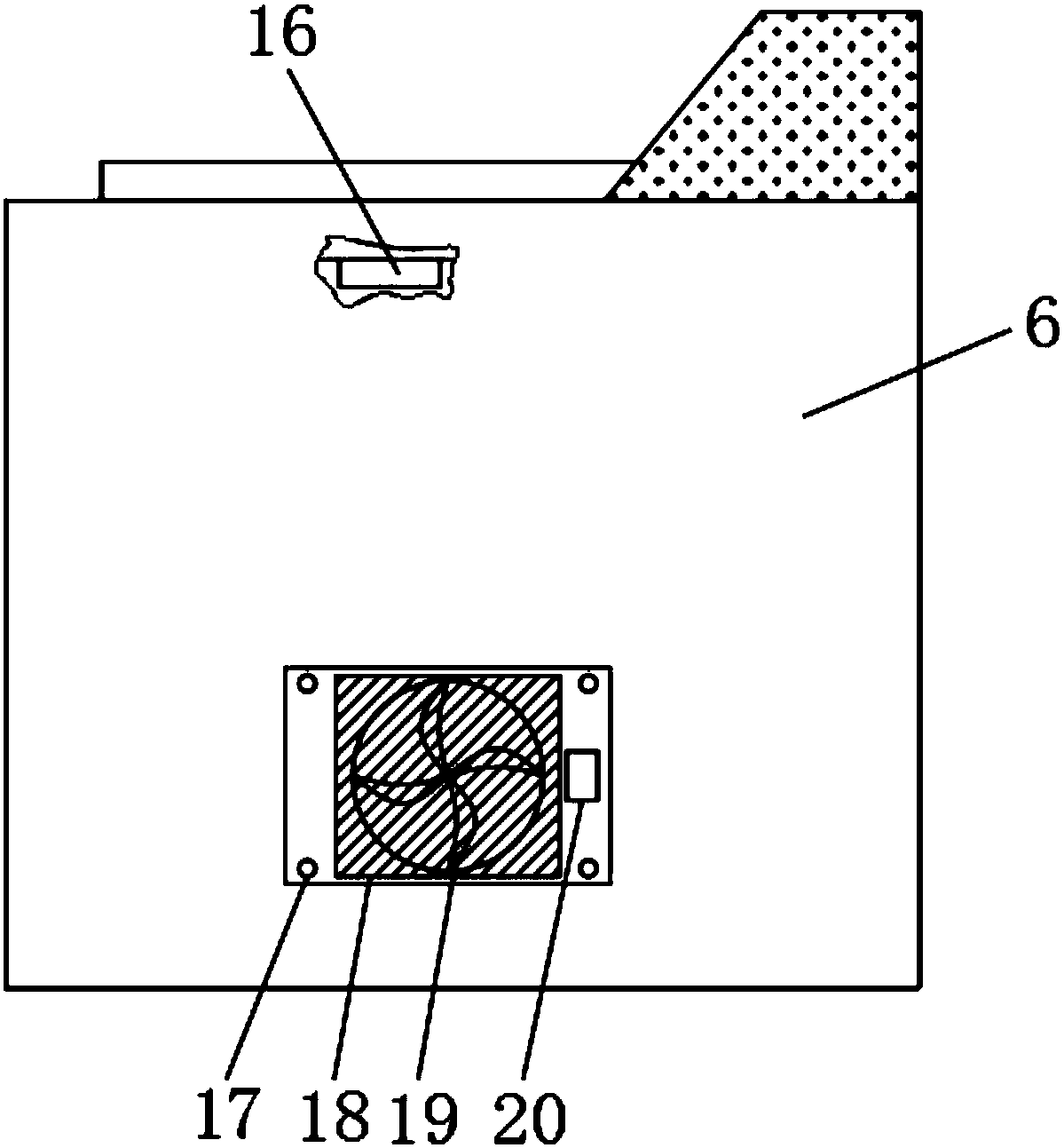
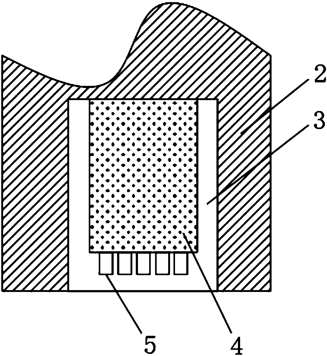
[0017] see Figure 1-3 , the present invention provides a technical solution: an automatic edge removal machine for rubber products, including an edge removal machine body 1, a leg 2, a groove 3, an electro-hydraulic rod 4, a pulley 5, a housing 6, a door 7, an electric Control box 8, power button 9, emergency stop button 10, TH6350 control panel 11, display screen 12, cylinder body 13, water spray bottle 14, discharge port 15, temperature sensor 16, fixing bolt 17, dust-proof net 18, cooling fan 19 and PLC controller 20, the bottom end of the edge removal machine body 1 is equipped with a leg 2, the inside of the leg 2 is provided with a groove 3, the inside of the...


PUM


Abstract

The invention discloses an automatic edge removal machine for a rubber product. The automatic edge removal machine comprises an edge removal machine body, support legs, grooves, electric hydraulic rods, sliding wheels, a TH6350 control panel, a temperature sensor, a dust screen, a heat dissipation fan and a PLC. The support legs are mounted at the bottom end of the edge removal machine body and internally provided with the grooves. Each electric hydraulic rod is mounted inside the corresponding groove. One end of each electric hydraulic rod is provided with the corresponding sliding wheels. Anelectric control cabinet is mounted at one side of the top end of a shell. The TH6350 control panel is mounted at the other side of a power button. The temperature sensor is mounted at the top end inside the edge removal machine body. The dust screen is mounted at the bottom of one side of the edge removal machine body through fixing bolts. The heat dissipation fan is mounted at the inner side ofthe dust screen. The PLC is mounted at one side of the dust screen. The automatic edge removal machine has the beneficial effects of being convenient to move, high in work stability and heat dissipation efficiency, capable of effectively guaranteeing use performance of equipment and convenient to use.

Description

technical field [0001] The invention relates to an edge-removing machine, in particular to an automatic edge-removing machine for rubber products. Background technique [0002] The rubber edge removal machine is a kind of aerodynamic principle, adopts the centrifugal principle, and there is an automatically controlled rotating disc in the cylinder to drive the rubber product to rotate at a high speed and continuously collide, so that the burrs and rubber products are separated from each other, so as to achieve the function of removing burrs , perfectly replaces the traditional manual, freezing and punching processes, and realizes the automatic edge removal machine for trimming and finishing rubber molded products. The existing automatic edge removal machine is large in size and inconvenient to move, and some equipment is equipped with pulleys. , the working stability is not high, and the heat dissipation efficiency of the equipment is low, which is not conducive to the use o...

Claims


Application Information

Patent Timeline
IPC IPC(8): B29C37/02H05K7/20
CPCB29C37/02H05K7/20136H05K7/20209
Inventor 王林甫
Owner 海宁市晨丰橡塑有限公司
Learn More