
Self-riveting machine for studs

A stud and riveting machine technology, applied in the direction of feeding device, positioning device, storage device, etc., can solve the problems of heavy workload and uneven product quality, so as to improve the workload, increase production efficiency, and reduce the number of operators Effect

Pending Publication Date: 2018-07-06
SHENZHEN HUNTKEY ELECTRIC
View PDF0 Cites 0 Cited by
  • Summary
  • Abstract
  • Description
  • Claims
  • Application Information

AI Technical Summary

Problems solved by technology

[0003] The purpose of the present invention is to provide a stud self-riveting machine, aiming to solve the technical problems of large workload and uneven product quality when the stud riveting in the prior art is manually operated

Method used


Image

  • Self-riveting machine for studs
  • Self-riveting machine for studs
  • Self-riveting machine for studs

Examples


Embodiment Construction

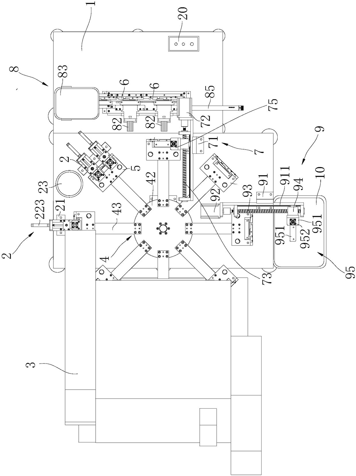
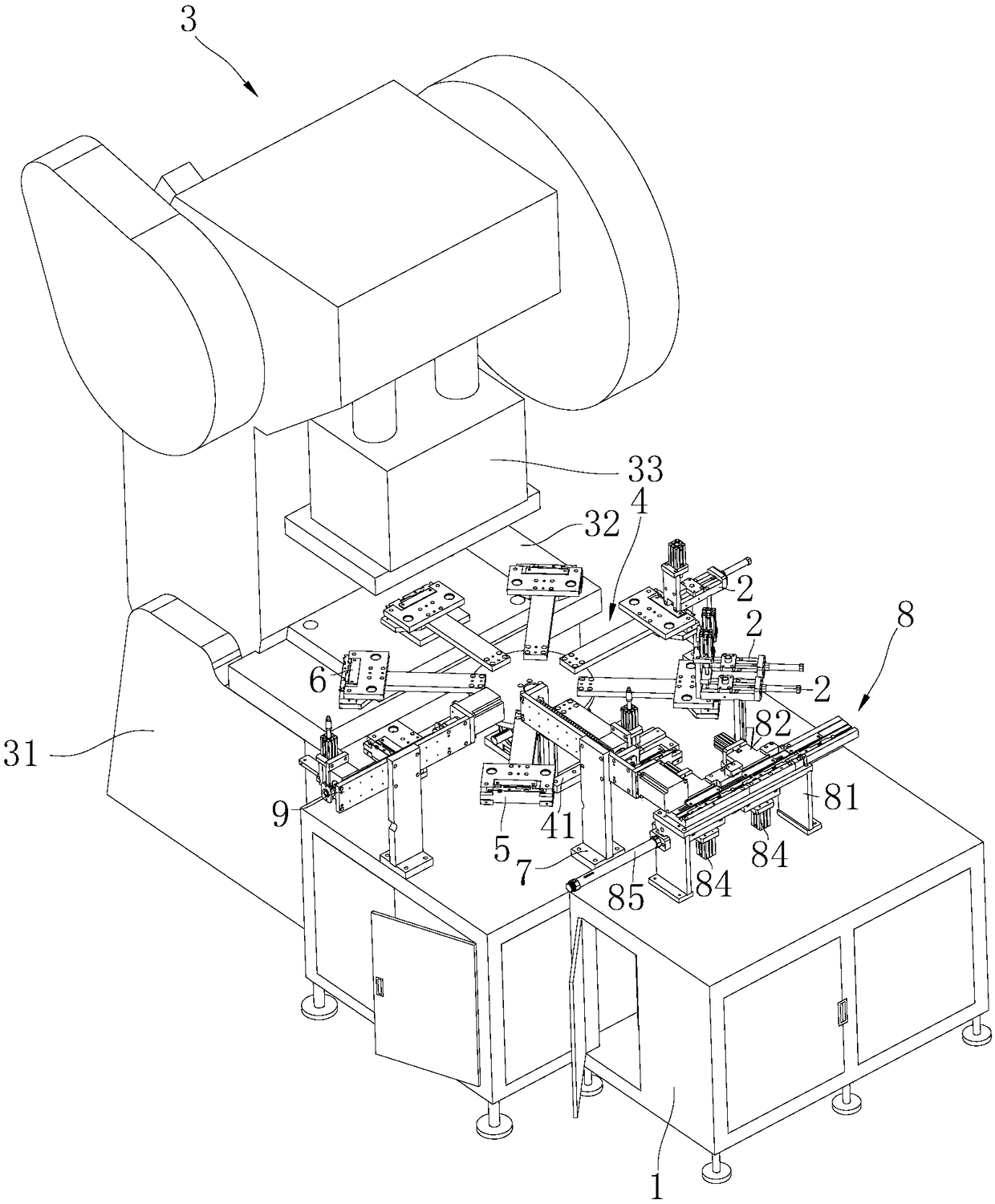
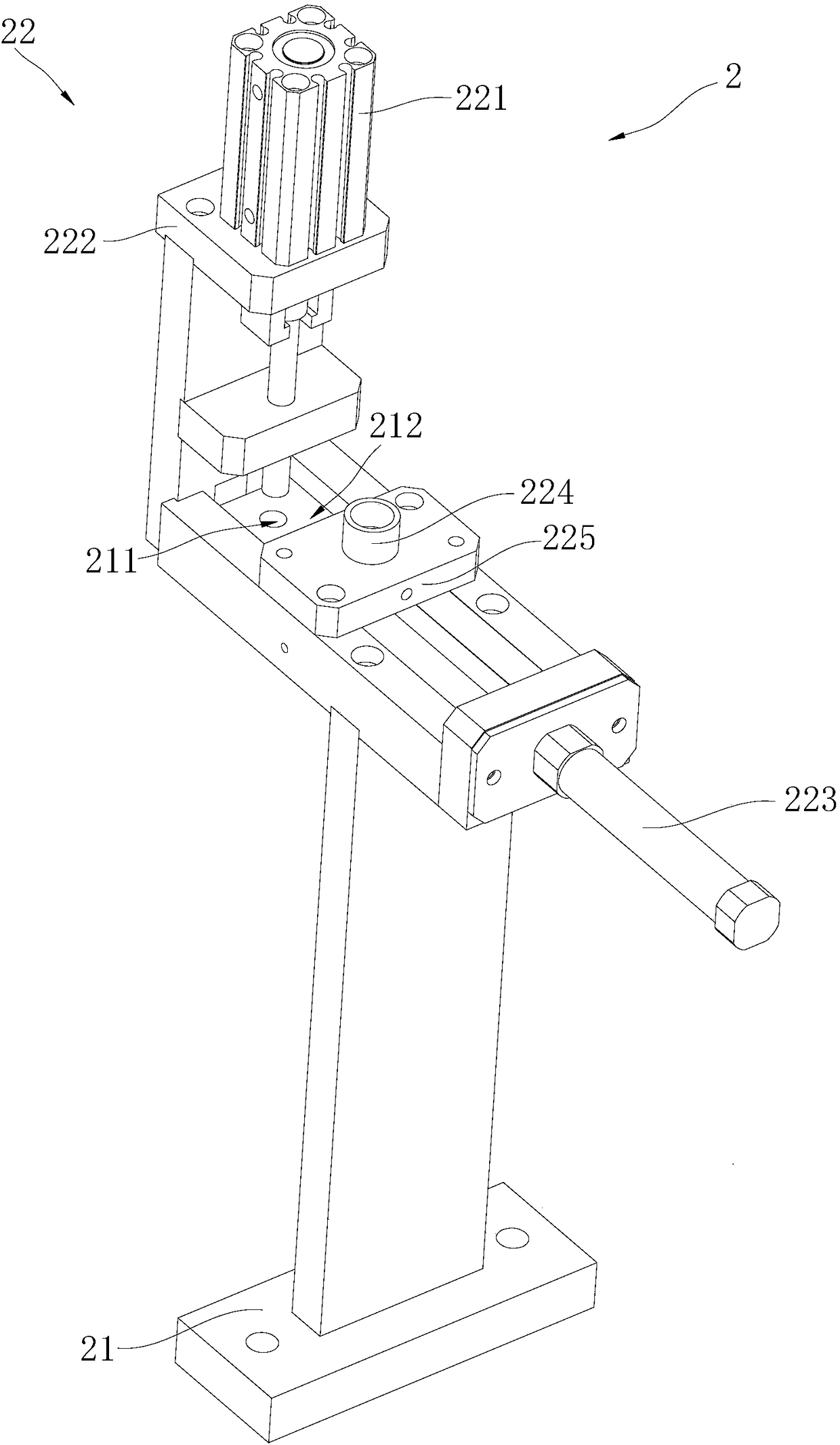
[0045] Embodiments of the present invention are described in detail below, examples of which are shown in the drawings, wherein the same or similar reference numerals designate the same or similar elements or elements having the same or similar functions throughout. Attached below by reference Figure 1-7 The described embodiments are exemplary and are intended to explain the present invention, but should not be construed as limiting the present invention.

[0046] In describing the present invention, it should be understood that the terms "length", "width", "upper", "lower", "front", "rear", "left", "right", "vertical", The orientation or positional relationship indicated by "horizontal", "top", "bottom", "inner", "outer", etc. are based on the orientation or positional relationship shown in the drawings, and are only for the convenience of describing the present invention and simplifying the description, rather than Nothing indicating or implying that a referenced device or...


PUM


Abstract

The invention belongs to the technical field of mechanical equipment and particularly relates to a self-riveting machine for studs. The self-riveting machine comprises a rack, a stud placing device, astamping and riveting device, a rotary driving device and multiple workpiece carriers for loading workpieces. The rotary driving device is fixed on the rack. The workpiece carriers are radially and fixedly installed on the rotary driving device and driven by the rotary driving device to rotate, the stud placing device and the stamping and riveting device are sequentially arranged at an interval in the rotating direction of the workpiece carriers, and the stud placing device is used for placing the studs on the workpieces, and the stamping and riveting device is used for connecting the studs with the workpieces in a punching and riveting manner. By the adoption of the self-riveting machine for the studs, the working load of operators is improved, the number of operators is reduced, the potential quality hazards are eliminated, the product quality is ensured, and the production efficiency is improved.

Description

technical field [0001] The invention belongs to the technical field of mechanical equipment, in particular to a stud self-riveting machine. Background technique [0002] The current stud riveting production mainly adopts the method of manually putting the stud into the product and then riveting it with a manually operated punching machine. Due to the negligence of manual work, the product is missed when tapping the product, and the stud is missed when the stud is riveted, and the stud is easily placed skewed during the riveting process of the product into the carrier, and the product quality is not easy to be guaranteed. . Moreover, manual work requires a large amount of manpower, a large workload, and high production costs. Contents of the invention [0003] The purpose of the present invention is to provide a stud self-riveting machine, aiming to solve the technical problems of heavy workload and uneven product quality when stud riveting is manually operated in the pri...

Claims


Application Information

Patent Timeline
IPC IPC(8): B23P19/02B23P19/00B23P23/04B21D39/00B21D43/00
CPCB21D39/00B21D43/00B21D43/006B23P19/001B23P19/02B23P23/04
Inventor 辜柱根叶江明
Owner SHENZHEN HUNTKEY ELECTRIC
Learn More