
Substrate adsorption mechanism, substrate transferring device and method

A technology of adsorption mechanism and substrate, which is applied in the field of substrate adsorption mechanism and substrate transfer device, can solve the problems of insufficient substrate adsorption effect, reduced substrate deformation, lack of flexibility, etc., to reduce the probability of vacuum leakage, reduce Effect of warpage deformation and improvement of product yield

Inactive Publication Date: 2018-07-03
SHANGHAI MICRO ELECTRONICS EQUIP (GRP) CO LTD
View PDF4 Cites 5 Cited by
  • Summary
  • Abstract
  • Description
  • Claims
  • Application Information

AI Technical Summary

Problems solved by technology

Due to the warping and deformation of the substrate, multiple suction nozzles close to the edge of the silicon wafer or glass substrate are tightly fitted together due to the weight of the substrate falling, while the suction nozzles far away from the edge do not fully establish a vacuum, resulting in vacuum leakage, which cannot reach the substrate adsorption. Effect
Using multiple lifting pins to support the base, although it can reduce the probability of vacuum leakage, is not conducive to reducing the deformation of the base and lacks flexibility. Moreover, it is not economical to use electrical control of lifting pins to control the deformation of the base.

Method used


Image

  • Substrate adsorption mechanism, substrate transferring device and method
  • Substrate adsorption mechanism, substrate transferring device and method
  • Substrate adsorption mechanism, substrate transferring device and method

Examples


no. 1 example

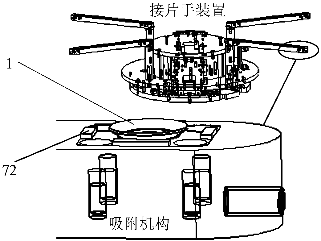
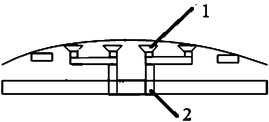
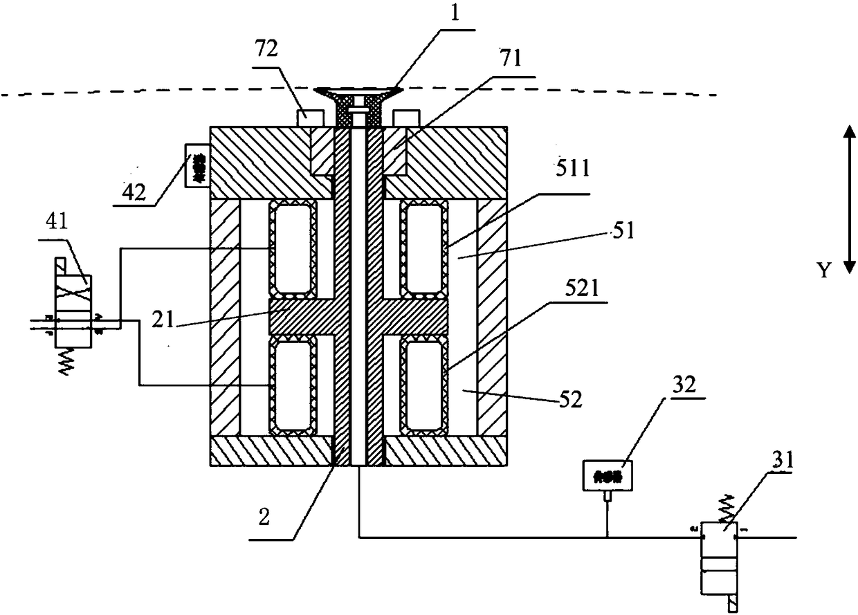
[0041] This embodiment proposes a substrate adsorption mechanism, which includes a support frame 7, a suction nozzle 1, an adsorption column 2, a first control loop and a second control loop. Specifically, such as image 3 or Figure 4As shown, the support frame 7 is a cylindrical support frame, and the present invention does not impose any restrictions on the shape and structure of the support frame 7; the support frame 7 is provided with a linear motion bearing 71, and the linear motion bearing 71 is sleeved on the adsorption column 2, Guide for the movement of the adsorption column 2. A limit stop 72 is also provided on the support frame 7, and the limit stop 72 is located under the suction nozzle 1, and is used for mechanical limit during the recovery process of the warping deformation of the substrate. Suction nozzle 1 is installed on the top of adsorption column 2, is used for adsorption substrate, and suction nozzle 1 structure can be cylinder, also can be cone, and t...

no. 2 example

[0057] This embodiment is a modification of the first embodiment.

[0058] Such as Figure 9 or Figure 10 As shown, different from the substrate adsorption mechanism in the first embodiment, the first flexible member in the first chamber 51 in this embodiment is the first spring 512, and the second flexible member in the second chamber 52 is the first spring 512. The second spring 522 plays the role of buffering and damping the base when the base is handed over. The present invention does not impose any limitation on the material, quantity and shape of the first spring 512 and the second spring 522 . The first spring 512 is arranged around the adsorption column 2, the top of the first spring 512 is connected to the support frame 7, and the bottom end is connected to the shoulder 21 of the adsorption column; the second spring 522 is arranged around the adsorption column 2, and its top is connected to the shoulder 21 of the adsorption column connect.

[0059] The adsorption...


PUM


Abstract

The invention provides a substrate adsorption mechanism, a substrate transferring device and a substrate transferring method. Through forming a first chamber and a second chamber in a supporting frame, the effects of buffering and shock absorption during substrate transferring are achieved, the warping deformation in the substrate adsorption process is adaptable, the warping deformation of a substrate can be flexibly adjusted after absorption, the transferring time is saved, and the transferring efficiency is improved, thereby improving product yield, and being economical and practical.

Description

technical field [0001] The invention relates to a substrate adsorption mechanism, a substrate handover device and method, in particular to an adsorption device and method with an adaptive function. Background technique [0002] As an important equipment in the field of microelectronics manufacturing, lithography equipment is mainly used for the processing and manufacturing of integrated circuit chips, flat panel display devices and other related semiconductor devices. As the main component of lithography equipment, the precision, speed and stability of the work table system determine the production efficiency of the lithography machine to a considerable extent. As an important part of the workpiece table subsystem, the Lift-PIN device is used to complete the work of loading and unloading the workpiece table. The splicing hand device is composed of a mounting base, a supporting component, a driving component, a measuring unit, an air control unit and an auxiliary supporting ...

Claims


Application Information

Patent Timeline
Patent Type & Authority Applications(China)
IPC IPC(8): H01L21/683H01L21/677G03F7/20
CPCG03F7/70716H01L21/67742H01L21/67775H01L21/6838
Inventor 黄正隆刘剑
Owner SHANGHAI MICRO ELECTRONICS EQUIP (GRP) CO LTD
Learn More