
3D (Three-dimensional) printing device for printing buildings

A 3D printing and ceramsite technology, which is used in ceramic molding machines, manufacturing tools, additive processing, etc., can solve the problem that the uniformity of concrete cannot be guaranteed, the integrity of the layered structure wall is poor, and the amount of concrete extrusion is difficult to control. and other problems, to ensure the integrity and stability, facilitate later decoration, and ensure the effect of flatness

Active Publication Date: 2018-07-03
CHONGQING CONSTR ENG NEW BUILDING MATERIALS +1
View PDF4 Cites 10 Cited by
  • Summary
  • Abstract
  • Description
  • Claims
  • Application Information

AI Technical Summary

Problems solved by technology

[0003] The integrity of this layered structure wall is poor, and it cannot achieve a good stability effect, and the structural strength of the wall needs to be further strengthened; the main factors affecting the structural strength of the wall are: during the printing process of building components, the traditional The design structure that uses pressure control to extrude concrete from the printing nozzle, because the uniformity of concrete cannot be guaranteed, when air enters the interior of the concrete, the pressure delivery capacity is poor, and the continuity of concrete extrusion is poor, thus affecting the wall The strength of the structure; the existing print heads print the building walls layer by layer. Since the cross section of the print head is circular, the cross section of the wall just printed on each layer is also approximately elliptical under the influence of gravity , so the bonding area between each layer of the wall is relatively small, which affects the structural strength of the wall
[0004] In addition, when it is necessary to turn the printing head or when the printing is finished, the amount of concrete extruded is difficult to control, which affects the forming effect of the wall

Method used


Image

  • 3D (Three-dimensional) printing device for printing buildings
  • 3D (Three-dimensional) printing device for printing buildings
  • 3D (Three-dimensional) printing device for printing buildings

Examples


Embodiment Construction

[0035] Below in conjunction with accompanying drawing and embodiment the technical scheme of the invention is further described:

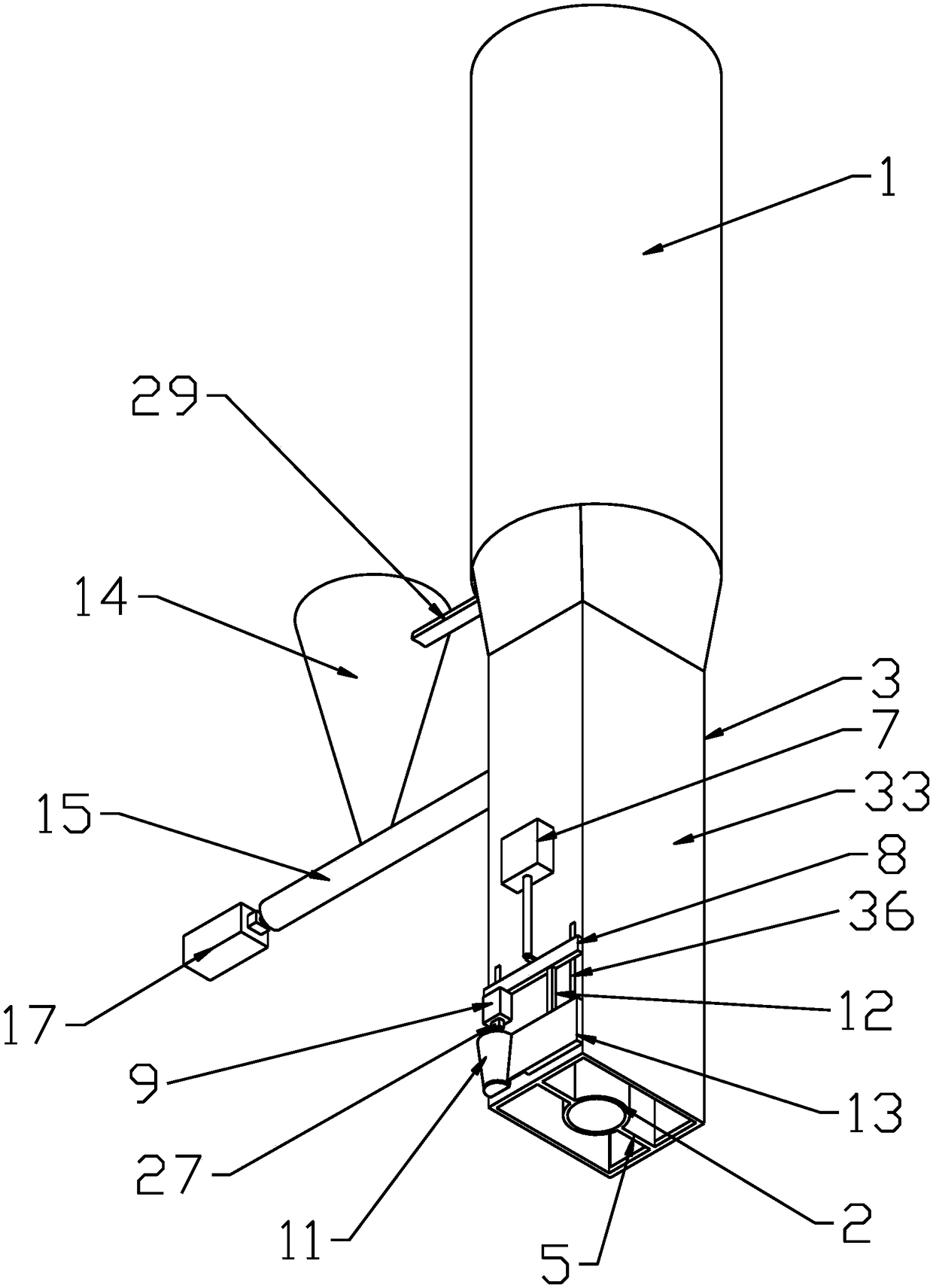
[0036] Such as Figure 1 to Figure 10 As shown, a 3D printing construction device includes a spray head 1 and a smoothing mechanism 30, wherein it also includes a ceramsite conveying mechanism, a screw drive device 4 is provided in the spray head 1, and the screw drive device 4 includes The screw driving rod 41 and the motor d42, the motor d42 is connected with the transmission d43, the speed changer d43 is connected with the upper end of the screw driving rod 41, the lower end of the spray head 1 is provided with the nozzle 3, and the lower end of the screw driving rod 41 extends to the nozzle 3, and the nozzle 3 is connected by the opposite It is surrounded by two parallel end plates and two opposite side plates 31, the two end plates are perpendicular to the movement direction of the nozzle 3, and the two end plates are provided with multiple The...


PUM


Abstract

The invention relates to the technical field of 3D (Three-dimensional) printer manufacturing, in particular to a 3D printing device for printing buildings. The 3D printing device for printing the buildings comprises a ceramsite conveying mechanism, wherein a spiral drive device is arranged in a spray head; a nozzle is arranged at the lower end of the spray head, and is formed by two end plates oppositely arranged in parallel and two sides plates oppositely arranged in a surrounding way; the two end plates are perpendicular to a movement direction of the nozzle; multiple bulge parts and sunkenparts are arranged on the two end plates long a length direction of the nozzle; the bulge part on one end plate and the sunken part on the other end plate are arranged correspondingly so as to realizethe matching of binding surfaces of each layer of wall body; a ceramsite discharge pipe and a support plate are arranged in the nozzle; the ceramsite discharge pipe is fixed into the nozzle through the support plate; and the upper end of the ceramsite discharge pipe is sealed. The 3D printing device for printing the buildings adopting the technical scheme provided by the intention has the advantages that a printed building wall is smooth in wall surface, good in attractiveness, high in structural strength, and good in forming effect.

Description

technical field [0001] The invention relates to the technical field of 3D printer manufacturing, in particular to a 3D printing construction device. Background technique [0002] A 3D printer mainly includes a printing structure, a forming printing table and a displacement adjustment mechanism of a printing head. As a 3D printing device for construction, it is mainly used to print building components, especially building walls as common components. The printing of building walls is mainly realized by layer-by-layer printing. After the printing is completed, the two sides of the building wall will be It shows an uneven state caused by layer-by-layer printing. In order to achieve a better aesthetic effect, this kind of building prefabricated wall will inevitably increase the subsequent decoration cost. [0003] The integrity of this layered structure wall is poor, and it cannot achieve a good stability effect, and the structural strength of the wall needs to be further streng...

Claims


Application Information

Patent Timeline
IPC IPC(8): B28B1/00B33Y30/00
CPCB28B1/001
Inventor 石从黎陈敬杨再富林宗浩樊先平
Owner CHONGQING CONSTR ENG NEW BUILDING MATERIALS
Learn More