
Light spot changing mechanism and 3D printing equipment provided with light spot changing mechanism

A technology of changing the light spot and adjusting the mechanism, which is applied in laser welding equipment, welding equipment, metal processing equipment, etc., can solve the problems of slow forming speed, restricting the speed and low efficiency of 3D printing rapid prototyping, and achieve the offset of focus. Effect

Pending Publication Date: 2018-07-03
易加三维增材技术(杭州)有限公司
View PDF4 Cites 2 Cited by
  • Summary
  • Abstract
  • Description
  • Claims
  • Application Information

AI Technical Summary

Problems solved by technology

The diameter of the laser cannot be changed, and there is only one diameter. When forming a large plane, the efficiency is very low and the forming speed is slow, which restricts the speed of rapid prototyping in 3D printing

Method used


Image

  • Light spot changing mechanism and 3D printing equipment provided with light spot changing mechanism
  • Light spot changing mechanism and 3D printing equipment provided with light spot changing mechanism

Examples


Embodiment Construction

[0023] Below, the present invention will be further described in conjunction with the accompanying drawings and specific implementation methods. It should be noted that, under the premise of not conflicting, the various embodiments described below or the technical features can be combined arbitrarily to form new embodiments. .

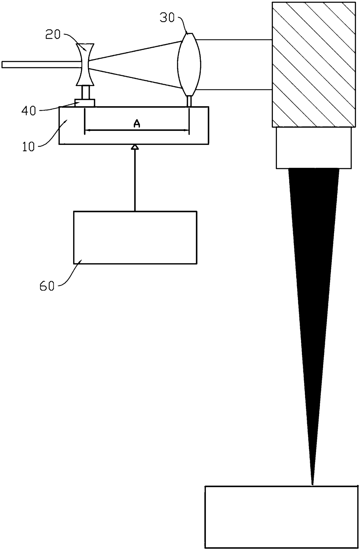
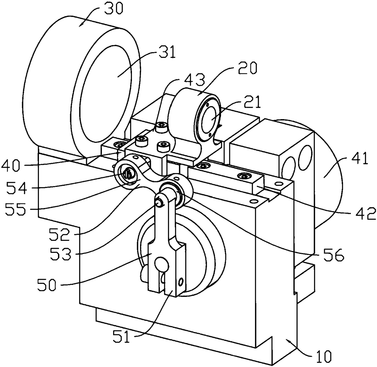
[0024] Such as figure 1 , figure 2 As shown, a 3D printing equipment facula variable mechanism includes a base 10 on which a first optical lens group 21, a second optical lens group 31 and an adjustment mechanism 40 are arranged. The adjustment mechanism 40 includes a power device 41, a transmission device 50. The guide rail 42 and the adjustment block 43 arranged on the guide rail 42, the power device is connected with the transmission device, the transmission device is connected with the adjustment block, the adjustment block is connected with the first optical lens group, and the power device drives the transmission device to drive the adjustment ...


PUM


Abstract

The invention discloses a light spot changing mechanism and 3D printing equipment provided with the light spot changing mechanism. A base table is provided with a first optical lens set, a second optical lens set and an adjusting mechanism. The adjusting mechanism comprises a power device, a transmission device, a guide rail and an adjusting block arranged on the guide rail. The power device is connected with the transmission device. The transmission device is connected with the adjusting block. The adjusting block is connected with the first optical lens set, the power device drives the transmission device to drive the adjusting block to move along the guide rail, and accordingly the distance between the first optical lens set and the second optical lens set can be adjusted. The light spot changing mechanism and the 3D printing equipment provided with the light spot changing mechanism have the beneficial effects that the first optical lens set linearly moves front and back along the guide rail under the action of the power device and the transmission device, the distance between the first optical lens set and the second optical lens set is changed, focus point deviation is achieved, and accordingly the size changes of light spots projected into a scanning system are achieved.

Description

technical field [0001] The present invention relates to the field of printing equipment, in particular to a spot variable mechanism and 3D printing equipment equipped with the spot variable mechanism. Background technique [0002] In laser 3D printing equipment, the traditional beam expander has a fixed optical path. After manually adjusting the focal length, the size of the exit spot is fixed, and it is also fixed during the processing of the 3D printing equipment. At present, the 3D printing industry is moving towards mass production, and there is a big bottleneck, which is the problem of printing efficiency. 3D printing needs to use laser scanning to print layer by layer, and in order to pursue precision and surface quality, the laser spot size often needs to be adjusted as small as possible. The smaller the laser spot, the longer the single-layer scanning path and the longer the scanning time, so the printing efficiency will not improve. The diameter of the laser canno...

Claims


Application Information

Patent Timeline
Patent Type & Authority Applications(China)
IPC IPC(8): B23K26/342B23K26/064B29C64/273B33Y30/00B22F3/105
CPCB23K26/064B23K26/342B33Y30/00B22F10/10B22F10/00B22F12/90B22F10/36B22F12/44B22F10/20Y02P10/25
Inventor 汪文涛高鹏项伟灿袁永恒张寅锋陈新新王李波候大坤陈士杰
Owner 易加三维增材技术(杭州)有限公司
Learn More