
Ultraviolet-visible spectrum in situ monitoring device capable of adjusting optical path and water quality multi-parameter measuring method

A spectrum in-situ, monitoring device technology, applied in the measurement of color/spectral characteristics, etc., can solve the problems of loss of measurement performance, invalid data, and inability to adjust the optical path adaptively.

Pending Publication Date: 2018-06-29
CHINESE RES ACAD OF ENVIRONMENTAL SCI
View PDF0 Cites 9 Cited by
  • Summary
  • Abstract
  • Description
  • Claims
  • Application Information

AI Technical Summary

Problems solved by technology

However, in actual monitoring applications, especially when there is a risk of water pollution or in-situ monitoring on a mobile carrier, the water quality parameters will fluctuate in a wide range. The range is fixed. Generally, the long optical path is suitable for the situation when the water quality parameters are at a low level, and the short optical path is suitable for the situation when the water quality parameters are at a high level. It cannot meet the ideal measurement performance at the same time when the water quality parameters are at high and low levels. , it is impossible to adjust the optical path adaptively under different water quality parameter levels
When water quality parameters fluctuate in a large range, using a fixed optical path for measurement may result in loss of measurement performance (reduced accuracy, precision), and may even result in invalid data

Method used


Image

  • Ultraviolet-visible spectrum in situ monitoring device capable of adjusting optical path and water quality multi-parameter measuring method
  • Ultraviolet-visible spectrum in situ monitoring device capable of adjusting optical path and water quality multi-parameter measuring method
  • Ultraviolet-visible spectrum in situ monitoring device capable of adjusting optical path and water quality multi-parameter measuring method

Examples


Embodiment Construction

[0029] In order to facilitate the understanding of the present invention, the present invention will be described more fully below with reference to the associated drawings. Preferred embodiments of the invention are shown in the accompanying drawings. However, the present invention can be embodied in many different forms and is not limited to the embodiments described herein. On the contrary, these embodiments are provided to make the understanding of the disclosure of the present invention more thorough and comprehensive.

[0030] It should be noted that when an element is referred to as being “fixed” to another element, it can be directly on the other element or there can also be an intervening element. When an element is referred to as being "connected to" another element, it can be directly connected to the other element or intervening elements may also be present.

[0031] Unless otherwise defined, all technical and scientific terms used herein have the same meaning as...


PUM


Abstract

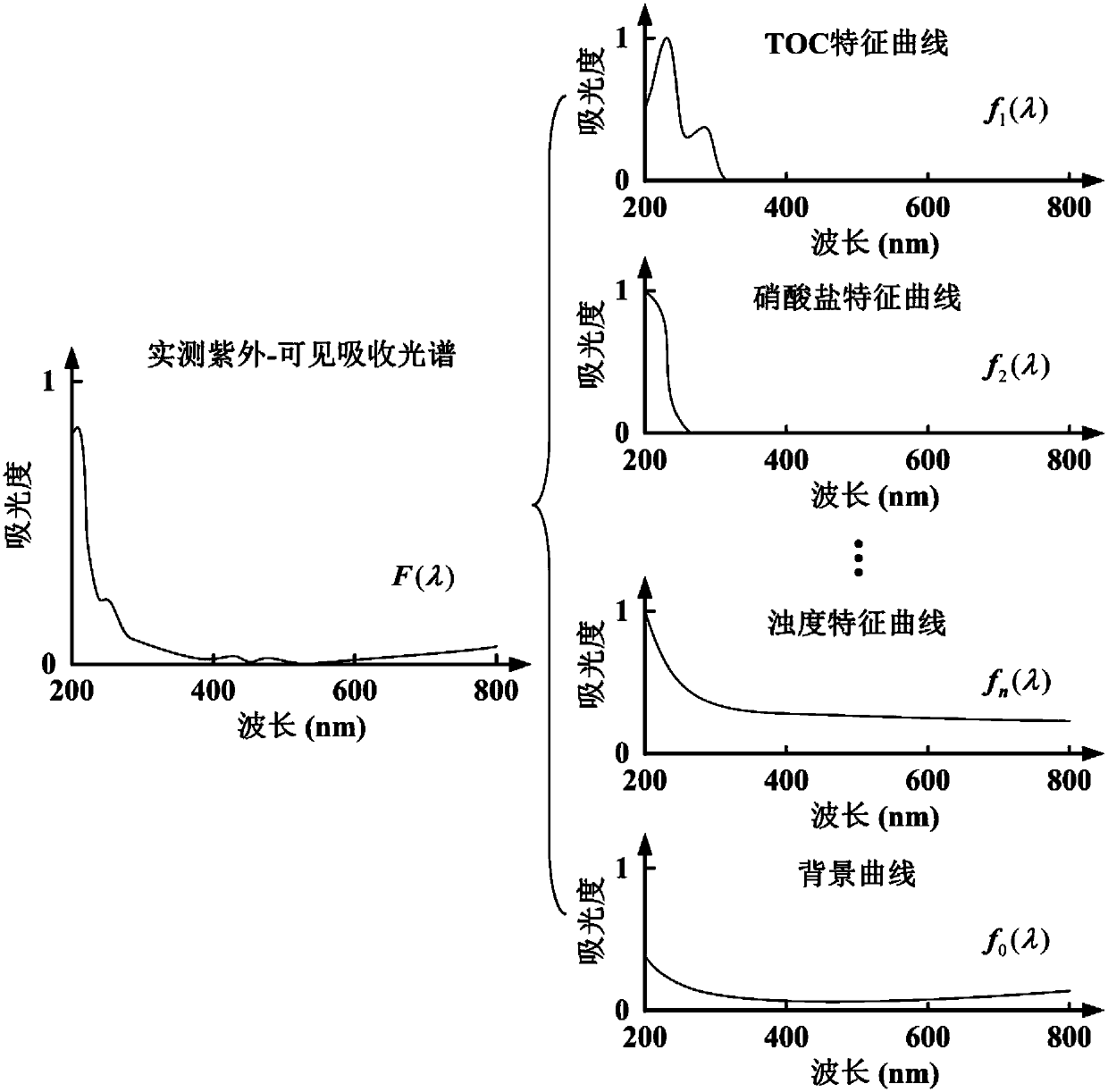
The invention discloses an ultraviolet-visible spectrum in situ monitoring device capable of adjusting an optical path and a water quality multi-parameter measuring method. The monitoring device comprises a monitoring part, a light source, a collimating lens, a converging lens, an emitting part, a flat field holographic concave grating and an image detector; a monitoring probe is arranged in waterto be detected; and a second sub-chamber is filled with the water to be detected. The light source is arranged for supplying illumination, the light emitted by the light source is collimated by the collimating lens to become parallel beams, the parallel beams pass through the water to be detected in the second sub-chamber, then are converged by the converging lens and are emitted from emitting slits of the emitting part, the light emitted from the emitting slits is divided through the flat field holographic concave grating and is imaged on a light-sensitive surface of the image detector, theimage detector converts light intensity signals with different wavelengths into electrical signals, namely an ultraviolet-visible spectrum, and a controller acquires and records ultraviolet-visible spectrum signals. The monitoring device is greatly improved in monitoring efficiency and high in measurement accuracy.

Description

technical field [0001] The invention relates to the field of environmental monitoring, in particular to an ultraviolet-visible spectrum in-situ monitoring device with adjustable optical path and a water quality multi-parameter measuring method. Background technique [0002] In the field of water environment monitoring, automatic monitoring of water bodies such as rivers, lakes, reservoirs, groundwater, and coastal waters includes sampling monitoring and in-situ monitoring. Sampling monitoring adopts the automatic sampling system to periodically collect water samples, and the monitoring equipment analyzes the water samples. There are problems such as long monitoring period, high power consumption of moving parts, complex system, large maintenance, and pipeline blockage and aging; in-situ monitoring It has unique advantages, including real-time monitoring, few moving parts, low power consumption, simple system, and low maintenance, especially when using ultraviolet-visible spe...

Claims


Application Information

Patent Timeline
IPC IPC(8): G01N21/33G01N21/31
CPCG01N21/31G01N21/33
Inventor 马俊杰王业耀孟凡生张铃松周岳溪石平
Owner CHINESE RES ACAD OF ENVIRONMENTAL SCI
Learn More