
Position monitoring method and system

A monitoring system and monitoring target technology, applied in traffic control systems, traffic control systems of road vehicles, vehicle position indication, etc., can solve problems such as high cost and complex implementation, and achieve cost reduction, simple comparison and operation process, and improved monitoring The effect of efficiency and reliability

Active Publication Date: 2006-11-08
HUAWEI TECH CO LTD
View PDF1 Cites 36 Cited by
  • Summary
  • Abstract
  • Description
  • Claims
  • Application Information

AI Technical Summary

Problems solved by technology

[0005] The purpose of the present invention is to solve the problem of complex implementation and high cost in the prior art when realizing the position monitoring of the monitoring target

Method used


Image

  • Position monitoring method and system
  • Position monitoring method and system
  • Position monitoring method and system

Examples


Embodiment Construction

[0046] In order to make the object, technical solution and advantages of the present invention clearer, the present invention will be further described in detail below in conjunction with the accompanying drawings and embodiments. It should be understood that the specific embodiments described here are only used to explain the present invention, not to limit the present invention.

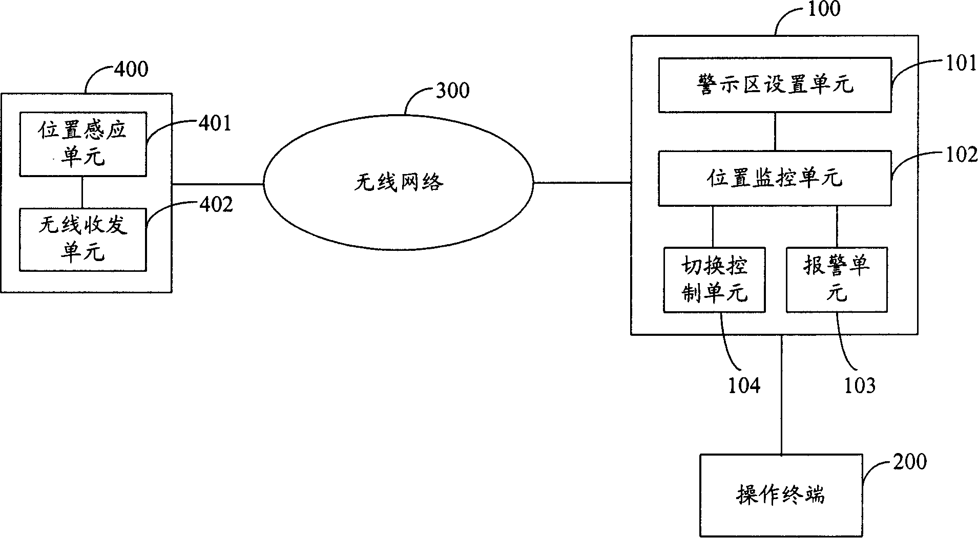
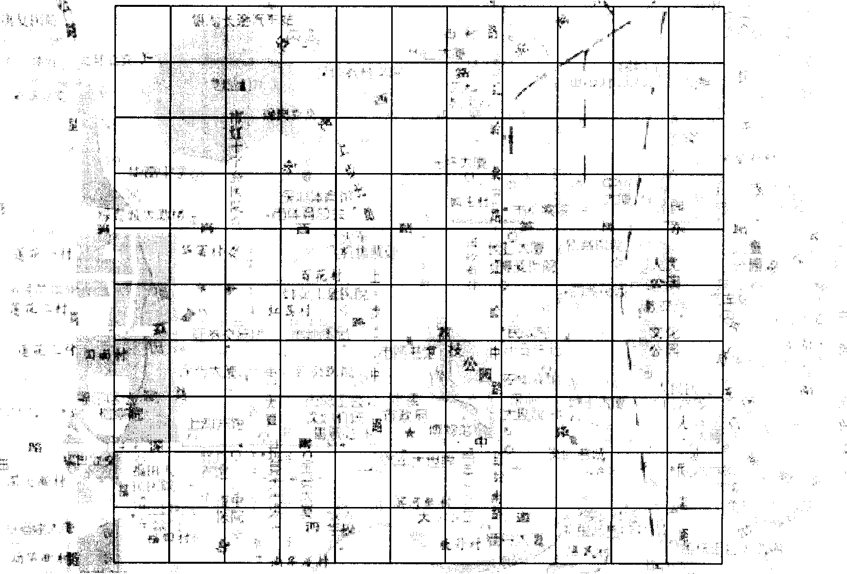
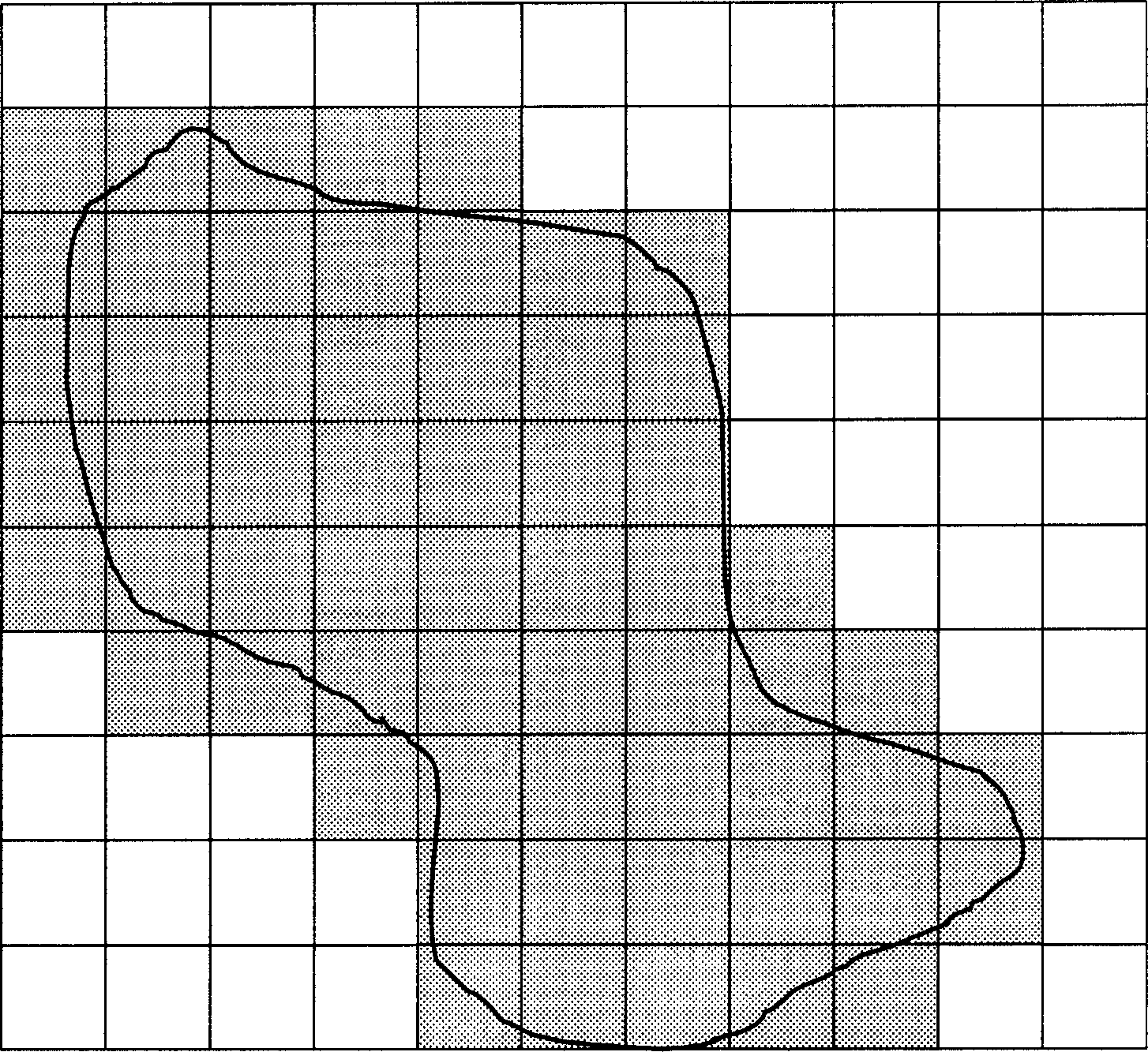
[0047] In the present invention, the mobile permission area of ​​the monitoring object is decomposed into a plurality of square warning areas, and the positioning parameters of only the quaternion value are determined in the warning area, so that the position of the monitoring object is monitored, which simplifies the calculation and comparison process, and at the same time By subdividing and merging the warning areas, it is possible to flexibly control the location changes of monitoring targets according to monitoring needs.

[0048] figure 1 A system structure for realizing the present invention...


PUM


Abstract

This invention provides a position monitor method and a system , in which, said method includes: A, designing a mobile admitted boundry of a monitor target and a mobile admitted region corresponding to said boundary, B, plotting out caution regions contained in the mobile admitted region including caution regions in the admitted region sphere and those passed by the boundary or pressing the edge, said caution region is a square and the transverse edge of said square is parallel to the woof, every caution is corresponding to a parameter including the longitudinal and latitude value of an any opposite angle of the square on an electronic map, C, following the position change of the monitor target to report the current position information including longitudinal and latitude value of the current position of the target, D, determining the caution region the target places based on the information of the target to issue beyong the mark alarm information when the target overstepping the mobile admitted region.

Description

technical field [0001] The invention belongs to the communication field, in particular to a method and system for monitoring the position of a monitoring target. Background technique [0002] With the increasing popularity of vehicles and other means of transportation, users such as bus companies, car rental companies or individuals wish to limit the provision of vehicles they manage or own to prevent vehicles from leaving the permitted area. For example, vehicles are only allowed to drive in the city or in some areas of the city, etc., to improve the safety of the vehicle. In addition to the need to monitor the location of the vehicle, it is also necessary to reasonably control the range of activities of the elderly, children, students or patients to ensure their safety. [0003] In the invention patent application titled "A Method for Determination of Vehicle Cross-Boundary Alarm", the application number is CN01127326.7, the polygonal driving area of ​​the vehicle is deco...

Claims


Application Information

Patent Timeline
Patent Type & Authority Applications(China)
IPC IPC(8): G08B25/00G08B21/18G08G1/097G08G1/123G08G1/13G08G1/137
Inventor 汤俊
Owner HUAWEI TECH CO LTD
Learn More