Heat exchanger for vehicle

A technology for heat exchangers and vehicles, applied in heat exchange equipment, indirect heat exchangers, heat exchanger types, etc., can solve the problem of low heat exchange performance, high manufacturing cost of shell and tube heat exchangers, and heat exchange tubes separation, etc.

Active Publication Date: 2018-06-29
HYUNDAI MOTOR CO LTD +1
View PDF9 Cites 2 Cited by
  • Summary
  • Abstract
  • Description
  • Claims
  • Application Information

AI Technical Summary

Problems solved by technology

[0008] At the same time, due to the excellent high-pressure resistance performance and component reliability of the shell-and-tube heat exchanger, the shell-and-tube heat exchanger can be widely used, and it can ensure a generally large installation space in factories or ships, so the shell-and-tube heat exchanger The heat exchanger can be used unlimitedly, but due to the relatively narrow installation space in the vehicle, when applying the shell-and-tube heat exchanger, the degree of freedom in design, the reliability of components, and the convenience of maintenance and repair have to be considered
[0009] Thus, in the shell-and-tube heat exchanger according to the related art, since the high-pressure (not less than 30 bar) coolant passes through the inner space of the case, the case must be a pressure-...

Method used


Image

  • Heat exchanger for vehicle
  • Heat exchanger for vehicle
  • Heat exchanger for vehicle

Examples


Embodiment Construction

[0045] Hereinafter, exemplary embodiments of the present invention will be described in detail with reference to the accompanying drawings. For reference, the size of components and the thickness of lines in the drawings may be exaggerated for ease of understanding. In addition, the terms used in the description of the present invention may be different depending on a user, an operator's intention, or a user's consideration of functions in the present invention. Therefore, terms should be defined according to the overall disclosure herein.

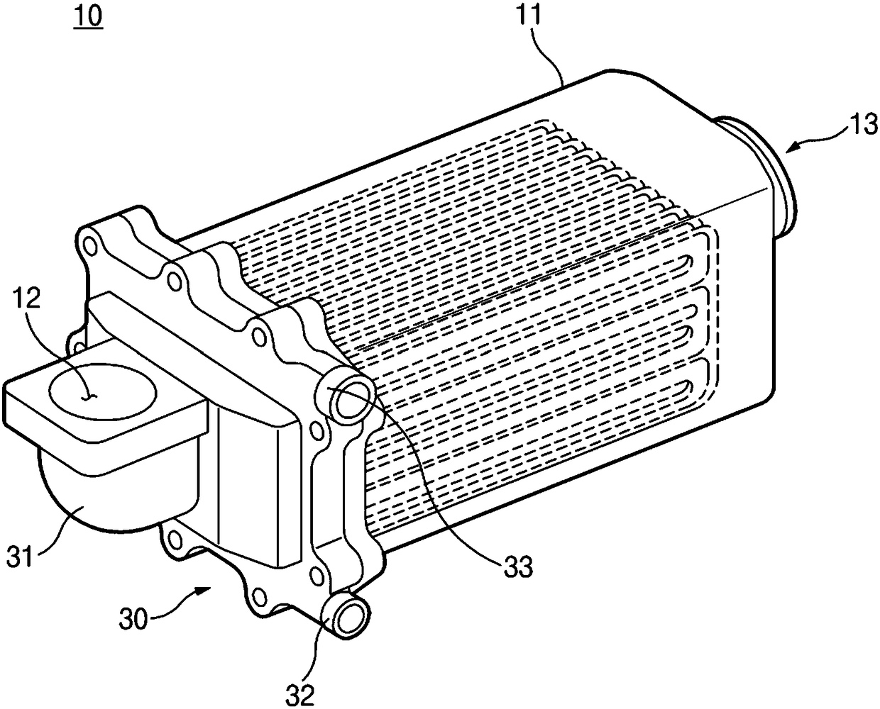
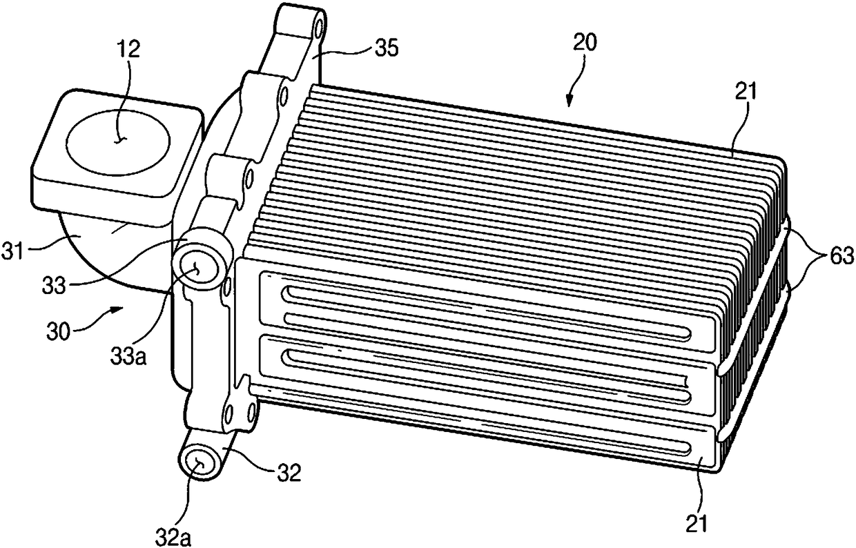
[0046] refer to Figure 1 to Figure 10 , the heat exchanger 10 for a vehicle according to various embodiments of the present invention may include a case 11 and a heat exchange core 20 installed in the case 11 .

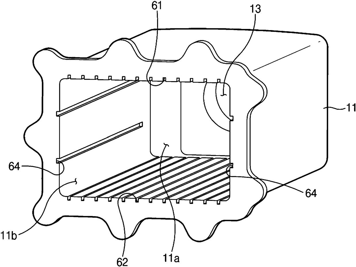
[0047] refer to figure 1 and image 3 , the housing 11 may have an inner space 11a through which the first fluid passes. The opening 11b can be installed at one end of the housing 11, the end 30 can be installed at the openi...


PUM


Abstract

The invention discloses a heat exchanger for a vehicle which includes: a housing having an interior space; a header installed at one end of the housing and having a first fluid inlet manifold; a second fluid inlet manifold; and a second fluid outlet manifold; and a heat exchange core installed in the interior of the housing and having a plurality of core elements spaced apart from each other. Theplurality of core elements are coupled to the header, and a plurality of first fluid passage, through which the first fluid passes, is respectively formed between the adjacent core elements. Each of the core elements has a second fluid passage, through which the second fluid flows, an inlet of the second fluid passage communicates with the second fluid inlet manifold, and an outlet of the second fluid passage communicates with the second fluid outlet manifold.

Description

[0001] Cross References to Related Applications [0002] This application is based on and claims the benefit of priority from Korean Patent Application No. 10-2016-0170232 filed in the Korean Intellectual Property Office on December 14, 2016, the entire disclosure of which is incorporated herein by reference. technical field [0003] The present invention relates to a heat exchanger for a vehicle, and more particularly, to a heat exchanger capable of improving heat transfer performance between two or more fluids. Background technique [0004] A heat exchanger is a device that transfers heat between two or more fluids. Heat exchangers can be used in various industrial fields such as vehicles, boilers, ships and facilities. [0005] Such heat exchangers include various types such as pin-and-tube heat exchangers, shell-and-tube heat exchangers, pin-type heat exchangers, and the like. [0006] The pin tube type heat exchanger can be manufactured simply, but the durability of t...

Claims


Application Information

Patent Timeline
IPC IPC(8): F28D7/08F28F9/26F28G9/00
CPCF28D7/085F28F9/26F28G9/00F28D2021/008F28D9/0031F02M26/32F28D9/0006F28F9/0075F28F2009/0287F28D7/0041F28F3/083F28F9/001F28D9/0081
Inventor 徐正玟
Owner HYUNDAI MOTOR CO LTD
Why Eureka
Try Eureka