Ash blowing explosion tank with rotatable partition plates

A technology of rotating clapboard and explosion tank is applied in the field of boiler pulse soot blowing, which can solve the problems of low filling degree of mixed gas, insufficient explosion power, low temperature dew point corrosion, etc., and achieve the effect of preventing low temperature dew point corrosion and improving the effect of soot blowing.

Pending Publication Date: 2018-06-29
XI AN JIAOTONG UNIV
View PDF0 Cites 3 Cited by
  • Summary
  • Abstract
  • Description
  • Claims
  • Application Information

AI Technical Summary

Problems solved by technology

The structure of the explosion tank in the domestic prior art is an open structure, and the gas outlet is connected to the chamber of the explosion tank. When the mixture of combustible gas and combustion-supporting gas fills the tank, the mixed gas will flow from the tank while filling the tank. The gas outlet of the body escapes, resulting in a low filling degree of the mixed gas in the tank, the pressure in the tank is not high, the power of the explosion is not enough, and with the prolongation of the use time, the dust accumulation on the inner wall of the explosion tank will gradually increase
In addition, due to the open structure of the explosion tank, when the pulse soot blower is not in operation, the sulfur trioxide in the flue gas in the boiler furnace will enter the tank through the gas outlet of the explosion tank. Due to the low temperature inside the tank, the sulfur trioxide Low temperature dew point corrosion caused by condensation in case of condensation

Method used


Image

  • Ash blowing explosion tank with rotatable partition plates
  • Ash blowing explosion tank with rotatable partition plates
  • Ash blowing explosion tank with rotatable partition plates

Examples


Embodiment Construction

[0021] The present invention will be described in further detail below in conjunction with the accompanying drawings and specific embodiments.

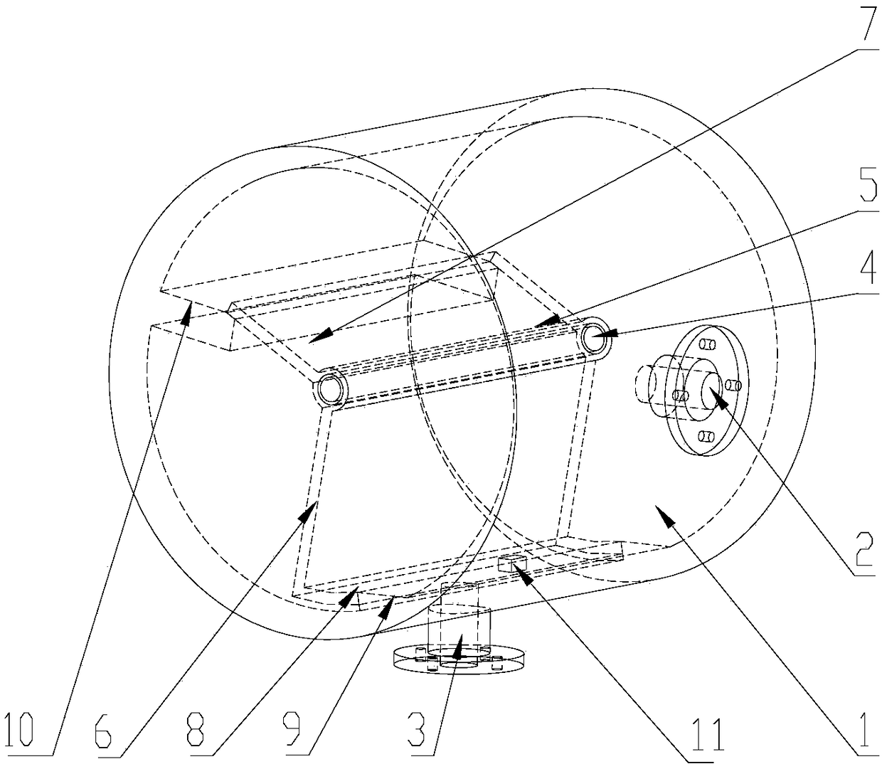
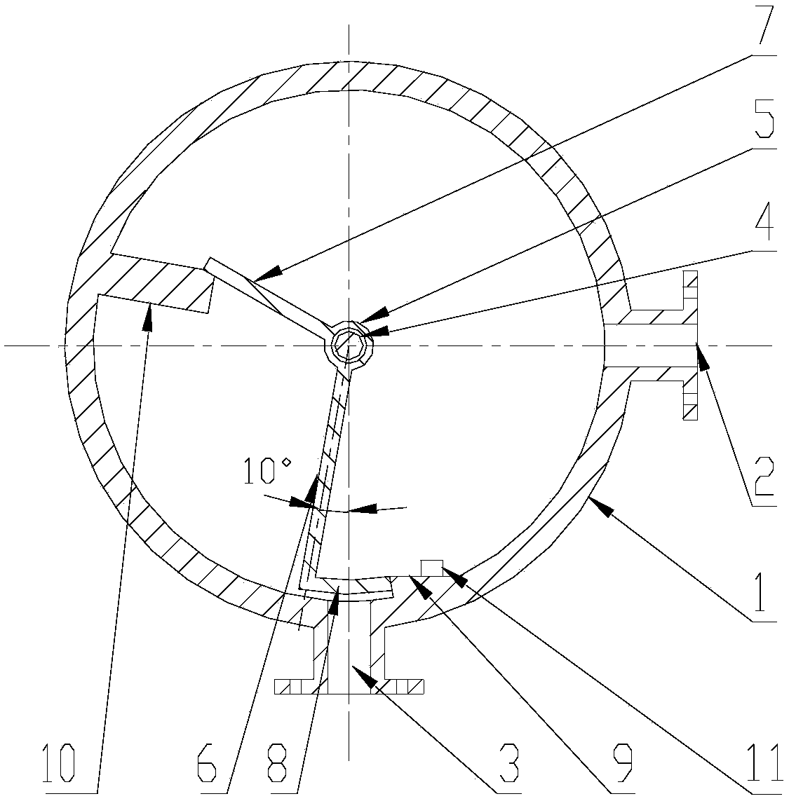
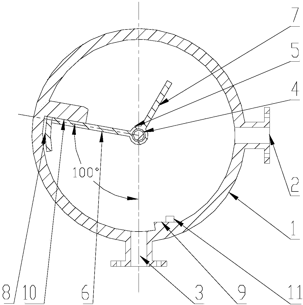
[0022] Such as figure 1 As shown, a soot blowing explosion tank with a rotatable partition in the present invention includes a tank body 1, an air inlet 2, an air outlet 3, and an ignition device 11; it also includes a shaft 4, a sleeve 5, and a first partition 6. The second partition 7 , the arc plate 8 , the first boss 9 , and the second boss 10 . The tank body 1 is a cylindrical structure with a chamber, arranged horizontally; an air inlet 2 and an air outlet 3 are arranged on the side wall of the tank body 1. As a preferred embodiment of the present invention, the direction of the air outlet 3 is vertical Downward, the air inlet 2 is perpendicular to the direction of the air outlet 3 . The shaft 4 is fixed to the tank body 1 and is located at the axis of the cylinder, and the sleeve 5 can freely rotate around the shaft 4 . The ...


PUM

PropertyMeasurementUnit
Radianaaaaaaaaaa

Abstract

The invention discloses an ash blowing explosion tank with rotatable partition plates. The ash blowing explosion tank comprises a tank body, an air inlet, an air outlet and an ignition device, and ischaracterized by further comprising a shaft, a sleeve pipe, the first partition plate, the second partition plate, an arc plate, a first boss and a second boss. In the natural state, due to the actionof gravity, the arc plate welded to the tail end of the first partition plate is attached to the first boss, the second partition plate is attached to the second boss, the air outlet is closed, a sealed cavity is formed, the fullness and pressure of mixed gas in the cavity are increased advantageously, and the situation that furnace hearth smoke enters the explosion tank and corrosion is caused can be prevented. When the explosion tank is ignited for explosion, the partition plates and the arc plate are impacted and can rotate clockwise, thus, the air outlet is opened, the first partition plate is impacted and collides with the second boss after rotating clockwise by 90 degrees, ash deposits on the inner wall face of the explosion tank is loosened favorably through sound waves and vibration which are caused by collision, the air inlet is blocked by the second partition plate during explosion, and the air inlet is kept communicating with the tank body cavity all the time.

Description

technical field [0001] The invention relates to the field of boiler pulse soot blowing, in particular to a soot blowing explosion tank with a rotatable partition. Background technique [0002] Pulse soot blower is one of the commonly used soot blowing equipment for boilers. It mainly uses combustible gas mixed with air or oxygen, and when it is ignited, it releases a shock wave with huge intensity. The shock wave can effectively clean the soot accumulated in the boiler. Explosion tank, also known as pulse tank, is a container used to carry mixed gas and explode. The structure of the explosion tank in the domestic prior art is an open structure, and the gas outlet is connected to the chamber of the explosion tank. When the mixture of combustible gas and combustion-supporting gas fills the tank, the mixed gas will flow from the tank while filling the tank. The gas outlet of the body escapes, resulting in a low filling degree of the mixed gas in the tank, the pressure in the t...

Claims


Application Information

Patent Timeline
IPC IPC(8): F23J1/00F23J3/00
CPCF23J1/00F23J3/00
Inventor 蒋文卓魏小林吴东垠
Owner XI AN JIAOTONG UNIV
Why Eureka
Try Eureka