
Reinforced cold-bent concrete-filled steel tube column, structure system and construction method

A technology for concrete-filled steel tubular columns and reinforced concrete, which is applied in the directions of columns, piers, pillars, etc., can solve the problems of poor construction quality, slow construction speed, poor seismic effect, etc. high effect

Pending Publication Date: 2018-06-29
姚攀峰
View PDF14 Cites 0 Cited by
  • Summary
  • Abstract
  • Description
  • Claims
  • Application Information

AI Technical Summary

Problems solved by technology

[0006] The purpose of the present invention is to provide a reinforced cold-formed steel tube concrete column and its structural system and construction method, to solve the technical problems of traditional structural systems such as fire prevention, poor anti-seismic effect, slow construction speed and poor construction quality

Method used


Image

  • Reinforced cold-bent concrete-filled steel tube column, structure system and construction method
  • Reinforced cold-bent concrete-filled steel tube column, structure system and construction method
  • Reinforced cold-bent concrete-filled steel tube column, structure system and construction method

Examples


Embodiment 1

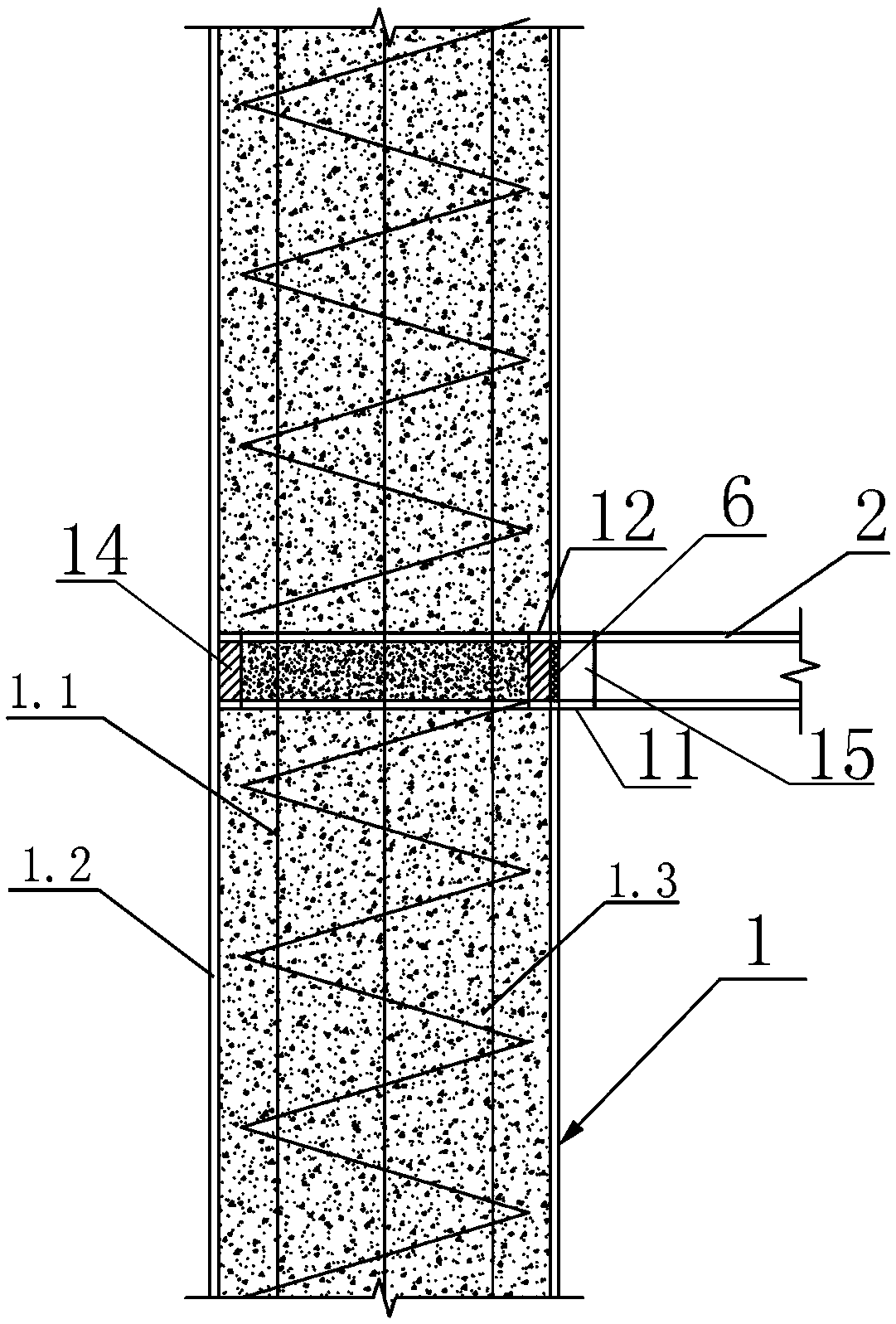
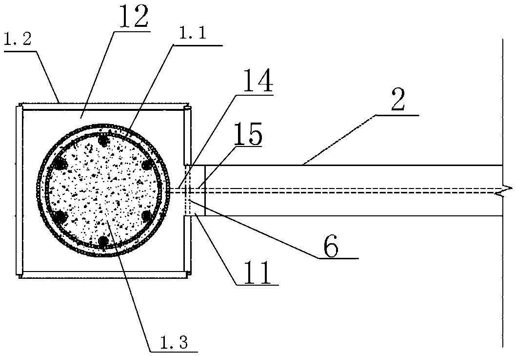
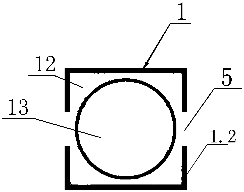
[0064] Such as Figure 1-3 As shown, this reinforced cold-formed steel pipe concrete column includes a steel pipe column main body 1.2 and column concrete 1.3 poured in the steel pipe column main body 1.2; the steel pipe column main body 1.2 is made of cold-formed steel pipe, and On the column main body 1.2, there is a hole 5 at the position connected with the structural beam to be installed; inside the steel pipe column main body 1.2, on the upper side and the lower side of the hole 5, there are respectively horizontal stiffening plates 12, two horizontal stiffening plates 12 A first vertical stiffening plate 14 is connected between them; the shape of the horizontal stiffening plate 12 is adapted to the cross-sectional shape of the steel pipe column main body 1.2, and the edge of the horizontal stiffening plate 12 is welded to the side wall of the steel pipe column main body 1.2; The plate surface of the horizontal stiffening plate 12 is provided with a perforation 13; the fi...

Embodiment 2

[0095] Such as Figure 4-7 As shown, this reinforced cold-formed steel pipe concrete column includes a steel pipe column main body 1.2 and column concrete 1.3 poured in the steel pipe column main body 1.2; the steel pipe column main body 1.2 is made of cold-formed steel pipe, and On the column main body 1.2, there is a hole 5 at the position connected with the structural beam to be installed; in the interior of the steel pipe column main body 1.2, on the upper side and the lower side of the hole 5, horizontal stiffening plates 12 are respectively provided, and the horizontal stiffening plates 12 Set along the cross-section transverse axis of the steel pipe column main body 1.2, the lateral sides of the horizontal stiffening plate 12 and the steel pipe column main body 1.2 are respectively spaced apart, and the gap between the horizontal stiffening plate 12 and the steel pipe column main body 1.2 forms the perforation 13. The end of the horizontal stiffening plate 12 protrudes ...


PUM


Abstract

The invention provides a reinforced cold-bent concrete-filled steel tube column, a structure system and a construction method. The reinforced cold-bent concrete-filled steel tubule column comprises asteel tube column main body and column concrete poured in the steel tube column main body; the steel tube column main body is made of steel tubes formed by cold bending, and holes are formed in the position, connected with a to-be-mounted structure beam, on the steel tube column main body; horizontal stiffening plates are arranged in the position, located on the upper sides and the lower sides ofthe holes, of the steel tube column main body; a first vertical stiffening plate is connected between the two horizontal stiffening plates; and penetrating holes are formed in the horizontal stiffening plates or the position between the horizontal stiffening plates and the steel tube column main body. According to the reinforced cold-bent concrete-filled steel tube column, the structure system andthe construction method, the technical problems that a traditional structure system is poor in fireproof and anti-seismic effect, low in construction speed and poor in construction quality are solved.

Description

technical field [0001] The invention belongs to the technical field of structural engineering, and in particular relates to a reinforced cold-formed steel pipe concrete column, a structural system and a construction method. Background technique [0002] The industrialization of construction is the focus of national construction and development. In the "Several Opinions of the Central Committee of the State Council on Further Strengthening the Management of Urban Planning and Construction" (February 6, 2016), it is clearly pointed out that "vigorously promote prefabricated buildings" and "encourage construction enterprises to assemble construction, on-site assembly", "building a national-level prefabricated building production base", "increasing policy support, and striving to make prefabricated buildings account for 30% of new buildings in about 10 years". [0003] my country is a country with frequent earthquakes. Earthquake disasters are the natural disasters that cause th...

Claims


Application Information

Patent Timeline
Patent Type & Authority Applications(China)
IPC IPC(8): E04C3/34E04B1/94
CPCE04B1/945E04C3/34
Inventor 姚攀峰
Owner 姚攀峰
Learn More