Hydraulic elevating device for iron tower

A technology of hydraulic lifting and iron tower, applied in the direction of lifting device, lifting frame, etc., can solve the problems of limited hydraulic lifting space, time-consuming and laborious scheduling and transfer, increase construction cost, etc., to reduce costs, use less tools, and avoid lateral sliding. Effect

Pending Publication Date: 2018-06-29
STATE GRID CORP OF CHINA +1
View PDF0 Cites 1 Cited by
  • Summary
  • Abstract
  • Description
  • Claims
  • Application Information

AI Technical Summary

Problems solved by technology

The lifting equipment is all large-scale machinery, and most of the iron towers that have settled are located in the suburbs or mountainous areas. It takes time and effort to dispatch and transfer, and it is even impossible to construct when the site situation is complicated; hydraulic equipment is smaller than lifting equipment, and construction is less difficult, but the hydraulic lifting space is limited. If the tilt angle of the iron tower is large, large hydraulic cylinders are required, and multi-cylinder operations are often required, and a large amount of equipment also needs to be carried, which greatly increases the construction cost

Method used


Image

  • Hydraulic elevating device for iron tower
  • Hydraulic elevating device for iron tower

Examples


Embodiment Construction

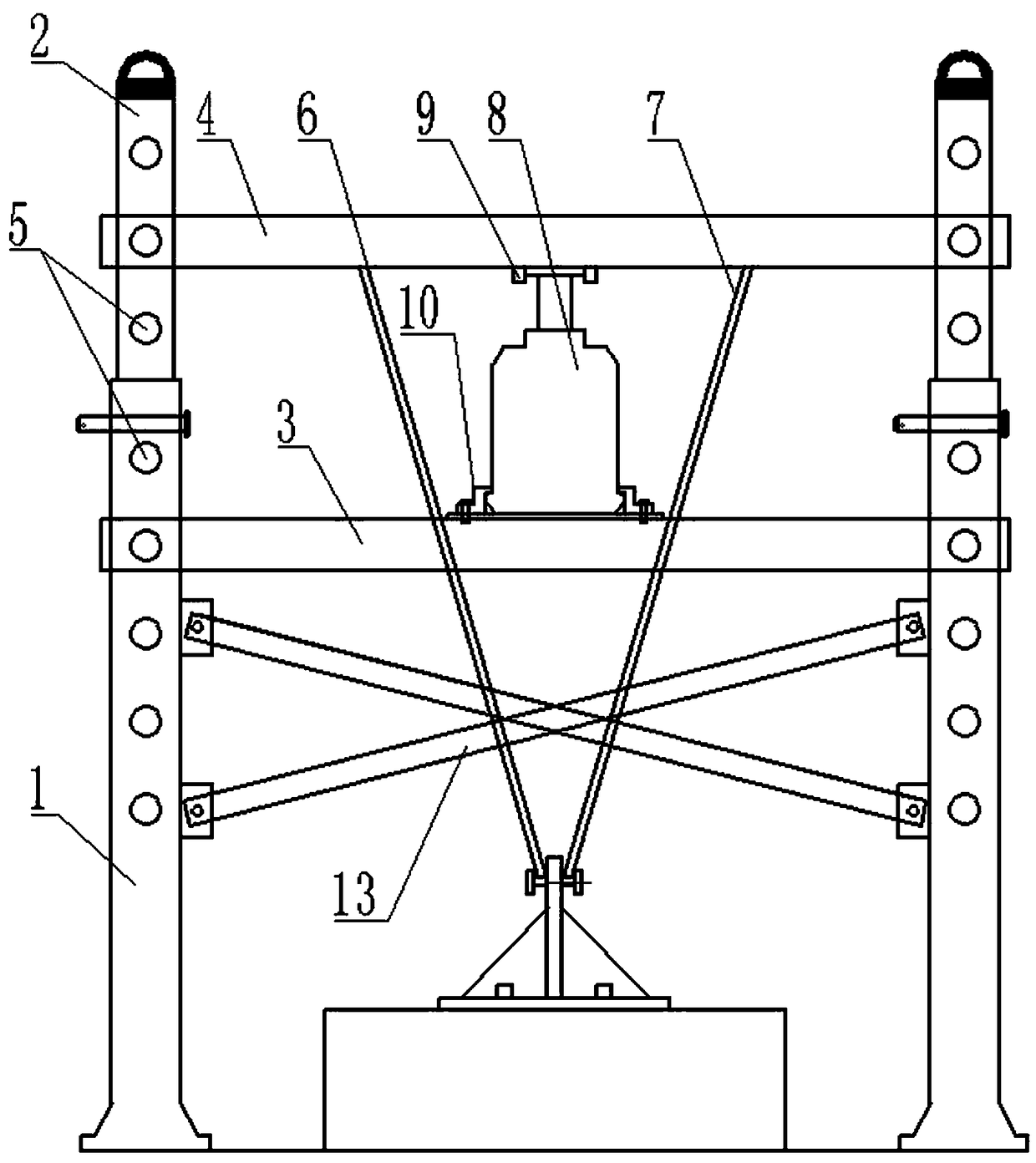
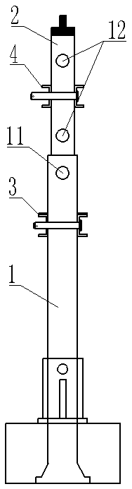
[0011] A hydraulic lifting device for an iron tower, comprising two base frames 1, the base frame 1 is equipped with a telescopic frame 2; Mounting holes 12 are arranged at intervals on the sides. Two stabilizing bars 13 are arranged crosswise between the corresponding underframes 1, the lower support beam 3 is installed on the underframe 1, the upper support beam 4 is installed on the telescopic frame, the upper support beam 4 and the lower support beam 3 are fixed through pin holes, and the upper support The first tie plate 6 and the second tie plate 7 are hinged on the upper beam 4, the hydraulic jack 8 is set on the lower support beam 3, the anti-slip base matching the bottom of the hydraulic jack 8 is fixedly installed on the top surface of the lower support beam, and the bottom surface of the upper support beam is fixed Install the anti-off cap 9 matched with hydraulic jack 8 piston rods.

[0012] During the lifting operation, the bottom frame 1 is fixed on the iron tow...


PUM


Abstract

The invention discloses a hydraulic elevating device for an iron tower. The hydraulic elevating device comprises two base brackets. An extending-and-contracting bracket is mounted in each base bracketin a sleeved manner. Pin holes are formed in the base brackets and the extending-and-contracting brackets in a spaced manner. A lower support beam is mounted at opposite positions of the base brackets. An upper support beam is mounted at opposite positions of the extending-and-contracting brackets. A first pull plate and a second pull plate are arranged on the upper support beam. A hydraulic jackis arranged on the lower support beam. According to the hydraulic elevating device, by means of the pin holes formed in the extending-and-contracting brackets and the base brackets in the spaced manner, a tower foot can be elevated level by level; the tower foot can be elevated by a large stroke through the small-size hydraulic jack; a small number of tools are used; the operating steps are simple; and maintenance cost of the power transmission iron tower is greatly lowered.

Description

technical field [0001] The invention relates to a maintenance device for a power transmission iron tower, in particular to a hydraulic lifting device for an iron tower. Background technique [0002] Transmission towers are often tilted due to ground subsidence and other reasons. Due to the large size and mass of the tower, it is necessary to use large lifting equipment to straighten it, or use hydraulic equipment to jack up the tower foot. The lifting equipment is all large-scale machinery, and most of the iron towers that have settled are located in the suburbs or mountainous areas. It takes time and effort to dispatch and transfer, and it is even impossible to construct when the site situation is complicated; hydraulic equipment is smaller than lifting equipment, and construction is less difficult, but the hydraulic lifting space is limited. If the inclination angle of the iron tower is large, large hydraulic cylinders are required, and multi-cylinder operations are often ...

Claims


Application Information

Patent Timeline
Patent Type & Authority Applications(China)
IPC IPC(8): B66F7/08
CPCB66F7/08
Inventor 任海平王小江冯启欣路明刘博苏鹏冯钢智利平
Owner STATE GRID CORP OF CHINA
Why Eureka
Try Eureka