
Novel type dual-spring constant-force-control clamping device

A clamping device, double spring technology, applied in decorative arts, processing models, manufacturing tools, etc., can solve the problems of easy to be broken, inconvenient adjustment, easy to cause accidents, etc., to achieve constant clamping force, simple structure, Easy-to-use effects

Inactive Publication Date: 2018-06-29
方流生
View PDF0 Cites 0 Cited by
  • Summary
  • Abstract
  • Description
  • Claims
  • Application Information

AI Technical Summary

Problems solved by technology

[0002] With the improvement of people's living standards, floor tiles, wall tiles and glass products for home decoration need to be carved or cut. Since floor tiles, wall tiles and glass are all brittle materials, when the clamping force is too large, it is easy to If it is crushed and the clamping force is too small, accidents will easily occur during the processing. Although the overflow valve can be used to control the clamping force in the hydraulic system or pneumatic system, the adjustment is not convenient enough, and the hydraulic system or pneumatic system Prone to failure, and difficult to repair when a failure occurs

Method used


Image

  • Novel type dual-spring constant-force-control clamping device
  • Novel type dual-spring constant-force-control clamping device
  • Novel type dual-spring constant-force-control clamping device

Examples


Embodiment Construction

[0013] The preferred embodiments of the present invention will be described in detail below in conjunction with the accompanying drawings, so that the advantages and features of the present invention can be more easily understood by those skilled in the art, so as to define the protection scope of the present invention more clearly.

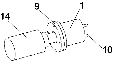
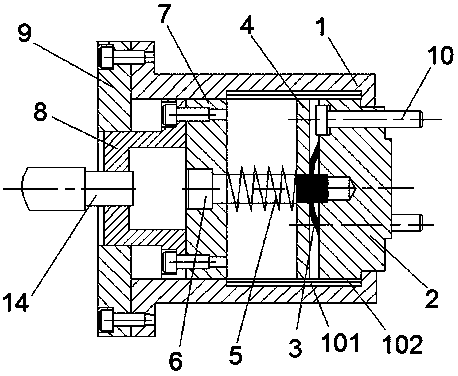
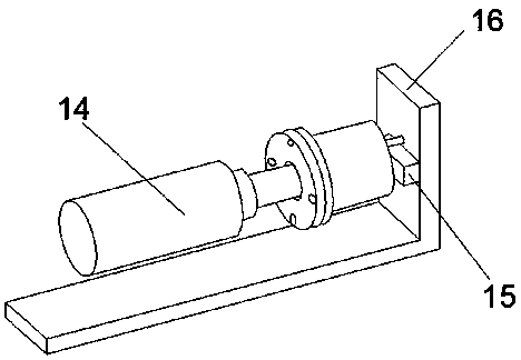
[0014] Such as Figure 1-Figure 4 As shown, a novel dual-spring type constant force control clamping device includes a hollow body 1, a clamping block 2, a force transmission assembly, a connecting block 8, a cover plate 9, a push rod 10 and a power device 14. The clamping block 2, the force transmission assembly, the connection block 8 and the cover plate 9 are installed in the body 1 from front to back, and the force transmission assembly includes a butterfly spring 3, a force transmission block 4, a cylindrical spring 5, a guide rod 6 and the guide block 7, the Belleville spring 3 is installed between the rear end of the clamping block 2 and t...


PUM


Abstract

The invention discloses a novel type dual-spring constant-force-control clamping device. The novel type dual-spring constant-force-control clamping device comprises a hollow body, a clamping block, aforce transmission assembly, a connecting block, a cover plate, an ejector rod and a power device, wherein the clamping block, the force transmission assembly, the connecting block and the cover plateare mounted in the body from front to rear; the force transmission assembly comprises a belleville spring, a force transmission block, a cylindrical spring, a guide rod and a guide block; the belleville spring is mounted between the rear end of the clamping block and the force transmission block; and the diameter of the position, close to the tail part, of the ejector rod is suddenly increased toform a step. The novel type dual-spring constant-force-control clamping device achieves the technical purpose of accurately controlling clamping force in a clamping process of a fragile material.

Description

technical field [0001] The invention relates to a clamping device for clamping workpieces, in particular to a novel dual-spring type constant force control clamping device. Background technique [0002] With the improvement of people's living standards, floor tiles, wall tiles and glass products for home decoration need to be carved or cut. Since floor tiles, wall tiles and glass are all brittle materials, when the clamping force is too large, it is easy to If it is crushed and the clamping force is too small, accidents will easily occur during the processing. Although the overflow valve can be used to control the clamping force in the hydraulic system or pneumatic system, the adjustment is not convenient enough, and the hydraulic system or pneumatic system It is prone to failure, and it is difficult to overhaul when a failure occurs. Contents of the invention [0003] The technical problem to be solved by the present invention is to provide a novel dual-spring type const...

Claims


Application Information

Patent Timeline
Patent Type & Authority Applications(China)
IPC IPC(8): B28D7/04B44B1/06B44B3/06
CPCB28D7/04B44B1/06B44B3/065
Inventor 方流生
Owner 方流生
Learn More