Eureka AIR delivers breakthrough ideas for toughest innovation challenges, trusted by R&D personnel around the world.

Dust collector

A vacuum cleaner and controller technology, applied in vacuum cleaners, exhaust diffusion devices, cleaning equipment, etc., can solve the problems of poor fan motor stability, damage to the vacuum cleaner, and large vibration amplitude, so as to reduce vibration, reduce work noise, and comfortably use. effects of the environment

Inactive Publication Date: 2018-06-29
JIANGSU MIDEA CLEANING APPLIANCES +1
View PDF5 Cites 0 Cited by
  • Summary
  • Abstract
  • Description
  • Claims
  • Application Information

AI Technical Summary

Problems solved by technology

The stability of the fan motor is poor, and the vibration amplitude is relatively large during the working process, which not only affects the dust collection effect of the vacuum cleaner, increases the working noise of the vacuum cleaner, but also easily causes damage to the vacuum cleaner

Method used

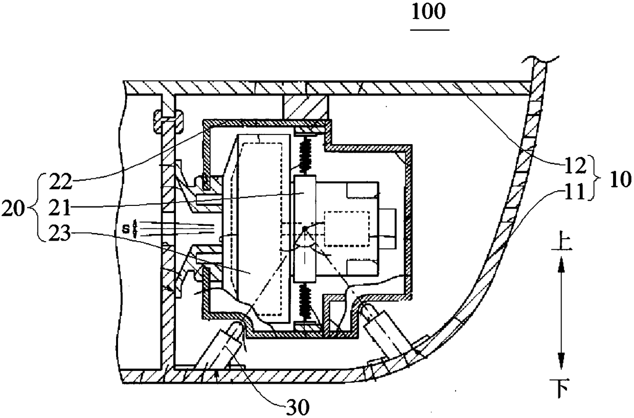
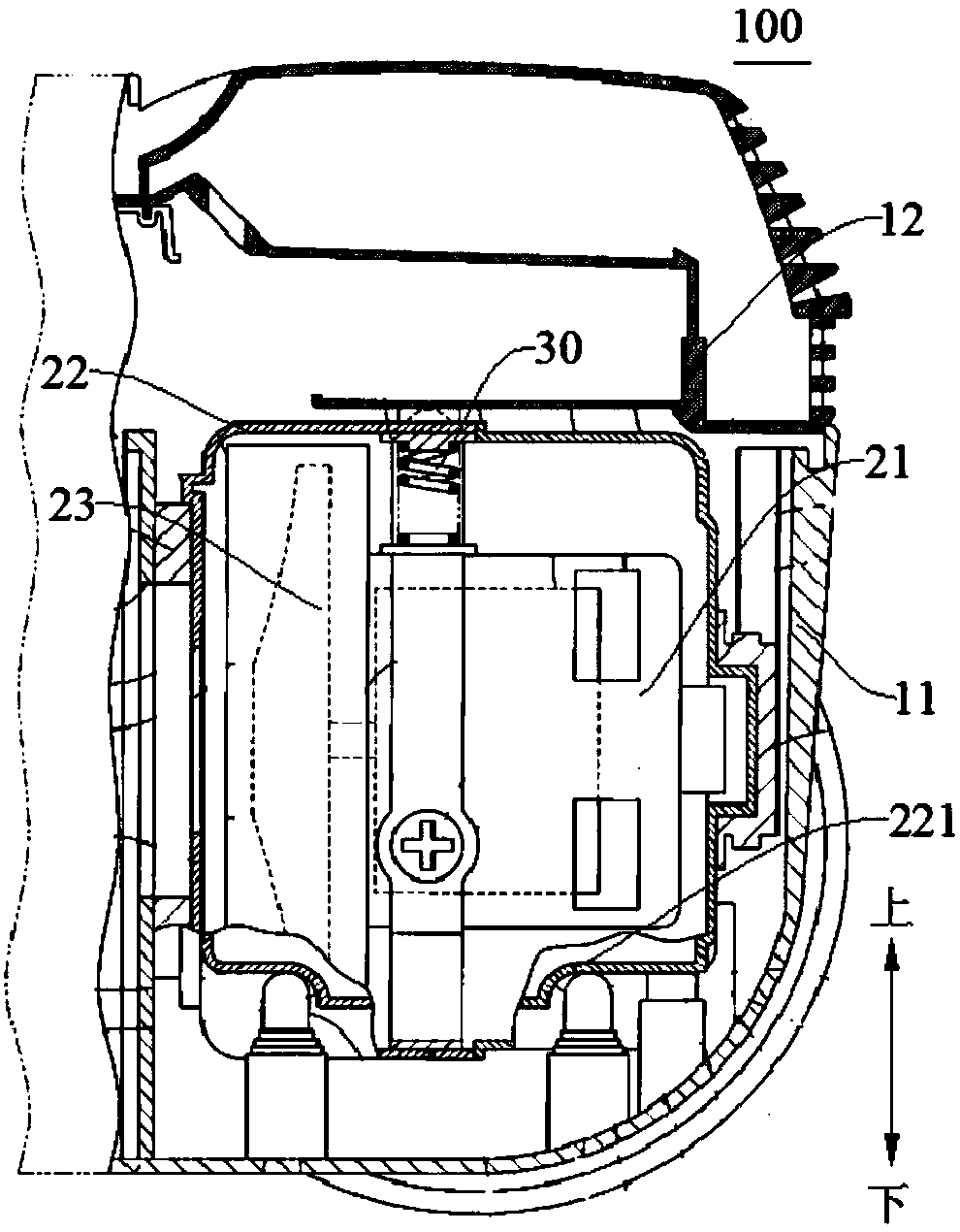
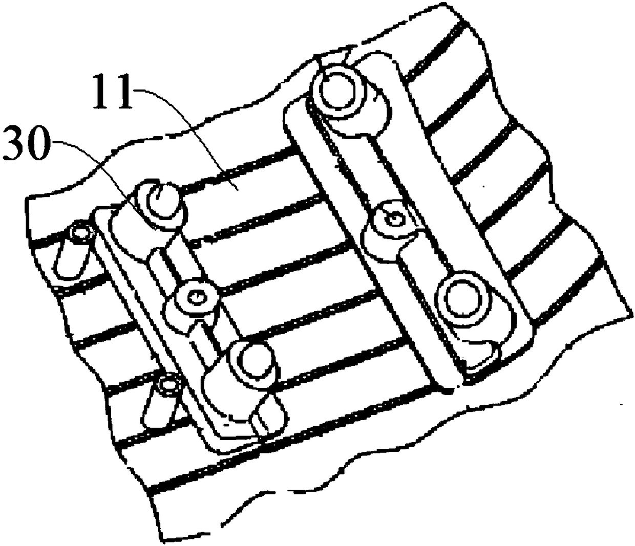

Image

  • Dust collector
  • Dust collector
  • Dust collector

Examples


Embodiment Construction

[0030] Embodiments of the present invention are described in detail below, examples of which are shown in the drawings, wherein the same or similar reference numerals designate the same or similar elements or elements having the same or similar functions throughout. The embodiments described below by referring to the figures are exemplary only for explaining the present invention and should not be construed as limiting the present invention.

[0031] In describing the present invention, it should be understood that the terms "center", "longitudinal", "transverse", "length", "width", "thickness", "upper", "lower", "front", " Back", "Left", "Right", "Vertical", "Horizontal", "Top", "Bottom", "Inner", "Outer", "Clockwise", "Counterclockwise", "Axial", The orientation or positional relationship indicated by "radial", "circumferential", etc. is based on the orientation or positional relationship shown in the drawings, and is only for the convenience of describing the present invent...


PUM


Abstract

The invention discloses a dust collector. The dust collector comprises a shell, a fan component and a plurality of elastic supporting parts. The shell is internally provided with a mounting cavity, the fan component is mounted in the mounting cavity and provided with a peripheral wall around the center axis, the elastic supporting parts are mounted on either the shell or the peripheral wall of thefan component, the elastic supporting parts are peripherally arranged at intervals along the fan component, and each elastic supporting part is compressed between the peripheral wall of the fan component and the mounting cavity. By the elastic supporting parts arranged between the outer wall of the fan component and the inner wall of the mounting cavity, in an operating vibration process of the fan component, vibration potential energy of the fan component is absorbed by the elastic supporting parts, and accordingly impact on the shell due to vibration of the fan component can be alleviated while vibration of the fan component can be alleviated as well, operating noise of the dust collector is weakened, and a comfortable use environment is provided for users.

Description

technical field [0001] The invention belongs to the technical field of household appliances, in particular, a vacuum cleaner is designed. Background technique [0002] The electric vacuum cleaner in the related art generates negative pressure through the rotation of the fan. After connecting the vacuum cleaner body and the connecting pipe, the dust in the air and the floor is sucked in from the end of the connecting pipe, and the dust in the filter is captured by a high-speed separator. The fan motor inside the motor cover is fixed by cylindrical rubber parts, multiple springs and the surrounding motor inner cover components. At the same time, the motor inner cover components are supported by even-numbered elastic top blocks on the lower periphery and even-numbered elastic wheels on the upper periphery. , and thus form a seal and fix with the host body. Through the rotation of the impeller of the fan motor, the circumferential direction (radial direction) of the electric bl...

Claims


Application Information

Patent Timeline
Patent Type & Authority Applications(China)
IPC IPC(8): A47L5/22A47L9/00
CPCA47L5/22A47L9/0081
Inventor 单洋阳戴君
Owner JIANGSU MIDEA CLEANING APPLIANCES
Why Eureka
Eureka Blog
Learn More