Eureka AIR delivers breakthrough ideas for toughest innovation challenges, trusted by R&D personnel around the world.

Multifunctional pin taking-out device

A pin remover and multi-functional technology, applied in the field of multi-function pin removers, can solve the problem of threats to the fixed firmness of insulator strings, safe operation of lines, W pins and R pins of insulator strings are prone to rust, fracture, and glass insulators are damaged by shock. and other problems, to achieve the effect of saving manpower and time, uniform force, and easy to carry.

Pending Publication Date: 2018-06-22
STATE GRID HEBEI ELECTRIC POWER CO LTD
View PDF5 Cites 2 Cited by
  • Summary
  • Abstract
  • Description
  • Claims
  • Application Information

AI Technical Summary

Problems solved by technology

[0002] Transmission lines run in the wild for a long time, affected by wind, frost, rain, snow and other natural environments, the W pins and R pins of the insulator strings are prone to rust and breakage, which seriously threatens the firmness of the insulator strings and the safety of the line It is a serious defect and needs to be dealt with in time
[0003] At present, there is no special canceler, and the replacement requires the completion of the equipotential operation or a power outage. The equipotential operation is complicated and requires a lot of manpower and material resources; if the power failure is performed, it is necessary to apply for a power outage maintenance of the line, which affects the normal power supply of the grid; use Fix the W pin and R pin by hitting with a common hammer, which is easy to damage the glass insulator

Method used


Image

  • Multifunctional pin taking-out device

Examples


Embodiment Construction

[0028] The technical solutions in the embodiments of the present invention will be clearly and completely described below with reference to the drawings in the embodiments of the present invention. Obviously, the described embodiments are only a part of the embodiments of the present invention, not all of the embodiments. Based on the embodiments of the present invention, all other embodiments obtained by those of ordinary skill in the art without creative efforts shall fall within the protection scope of the present invention.

[0029] Many specific details are set forth in the following description to facilitate a full understanding of the present invention, but the present invention can also be implemented in other ways different from those described herein, and those skilled in the art can do so without departing from the connotation of the present invention. Similar promotion, therefore, the present invention is not limited by the specific embodiments disclosed below.

[...


PUM


Abstract

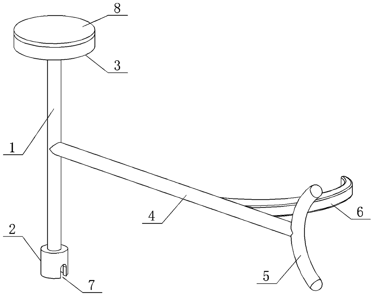
The invention discloses a multifunctional pin taking-out device, and relates to the technical field of electric maintenance tools. The multifunctional pin taking-out device comprises a first connecting bar, a first hammer head, a stress balance block, a second connecting bar, a second hammer head and a pinch bar. The first hammer head is arranged at the lower end of the first connecting bar. The stress balance block is arranged at the upper end of the first connecting bar. The front end of the second connecting bar is arranged in the middle of the first connecting bar. The second hammer head is arranged at the rear end of the second connecting bar. The pinch bar is arranged on the rear portion of the second connecting bar. According to the multifunctional pin taking-out device, through thefirst connecting bar, the first hammer head, the stress balance block, the second connecting bar, the second hammer head and the pinch bar, strain insulator string pins W and R are replaced in an electrification manner; operation is simple, convenient and rapid; manpower and time are saved; power grid operation reliability is guaranteed; carrying is convenient; the situation that insulators of glass materials are damaged by vibration is avoided; and use is safe and reliable.

Description

technical field [0001] The invention relates to the technical field of electric power maintenance tools, in particular to a multi-function detent. Background technique [0002] Transmission lines operate in the wild for a long time. Affected by the natural environment such as wind, frost, rain and snow, the W pins and R pins of the insulator strings are prone to corrosion and breakage, which seriously threatens the firmness of the insulator strings and the safety of the lines. The operation is a serious defect and needs to be dealt with in time. [0003] At present, there is no special canceller. When replacing, the equipotential operation needs to be completed or the power outage is performed. The operation of the equipotential operation is complicated and requires a lot of manpower and material resources; if the power outage is performed, it is necessary to apply for line outage maintenance, which affects the normal power supply of the power grid; use Fixing the W pin and...

Claims


Application Information

Patent Timeline
Patent Type & Authority Applications(China)
IPC IPC(8): B25B27/02
CPCB25B27/02
Inventor 程旭李涛刘兆威郭超寇马军何义良赵建辉高冰尚建广张沛楠
Owner STATE GRID HEBEI ELECTRIC POWER CO LTD
Why Eureka
Eureka Blog
Learn More