
Clamping device for thin-wall variable-section pipe

A clamping device and variable cross-section technology, applied in auxiliary devices, auxiliary welding equipment, welding/cutting auxiliary equipment, etc., can solve the problems of low operation efficiency, time-consuming and labor-intensive, low processing accuracy, etc., to improve versatility and stability. Sex, weight reduction effect

Pending Publication Date: 2018-06-22
ZHEJIANG UNIV OF TECH
View PDF0 Cites 11 Cited by
  • Summary
  • Abstract
  • Description
  • Claims
  • Application Information

AI Technical Summary

Problems solved by technology

[0003] The purpose of the present invention is to solve the problems of low processing accuracy, low operation efficiency, time-consuming and labor-intensive problems when welding thin-walled variable-section pipes by manual positioning, and propose a kind of welding, which has certain versatility and can be applied to certain pipe fittings. Clamping device for thin-wall variable-section tubes with a wide range of sizes and accurate positioning, which can improve welding accuracy and operating efficiency

Method used


Image

  • Clamping device for thin-wall variable-section pipe
  • Clamping device for thin-wall variable-section pipe
  • Clamping device for thin-wall variable-section pipe

Examples


Embodiment Construction

[0026] The present invention will be described in detail below according to the accompanying drawings and preferred embodiments, and the purpose and effect of the present invention will become clearer. The present invention will be further described in detail below in conjunction with the accompanying drawings and embodiments. It should be understood that the specific embodiments described here are only used to explain the present invention, not to limit the present invention.

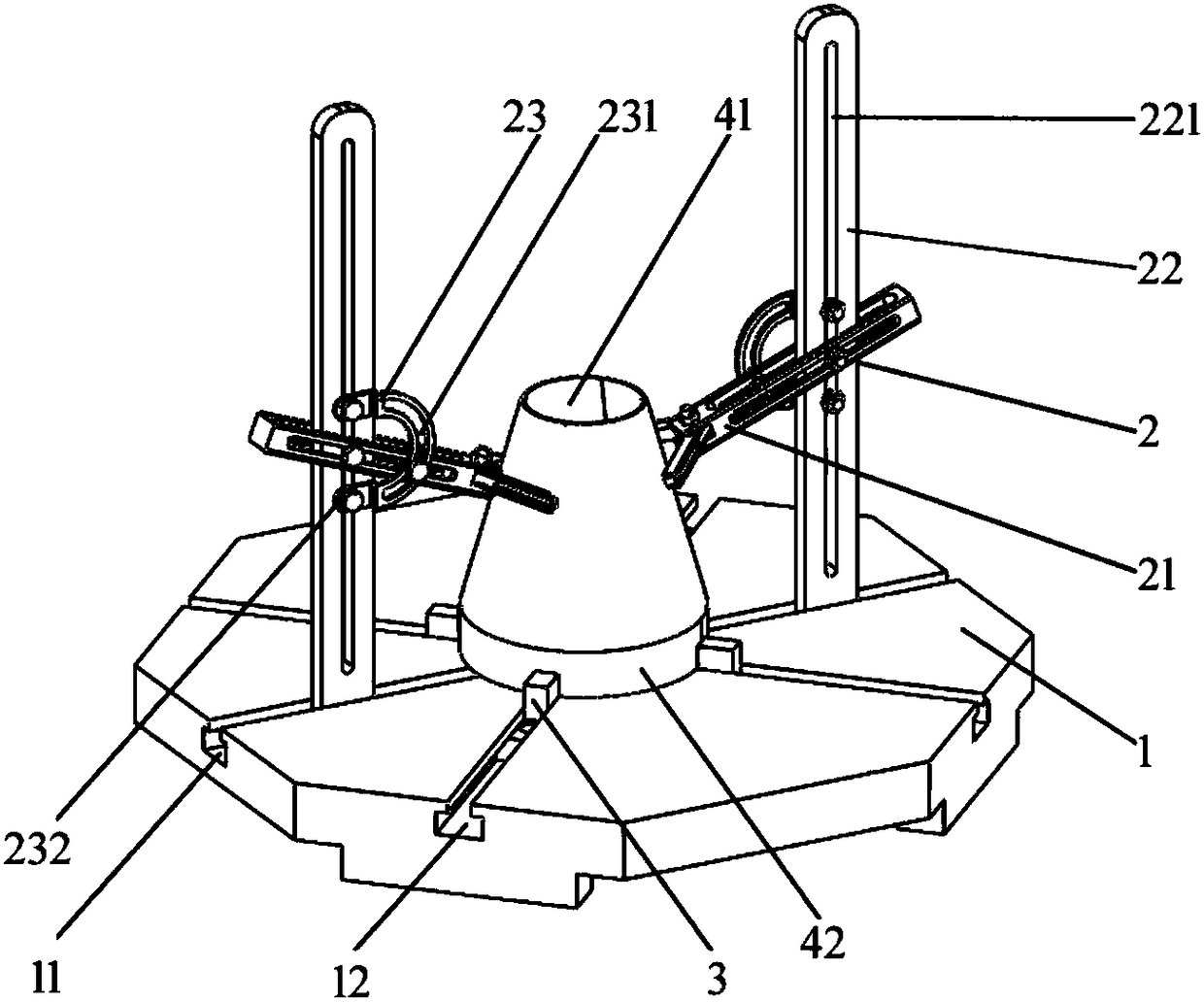
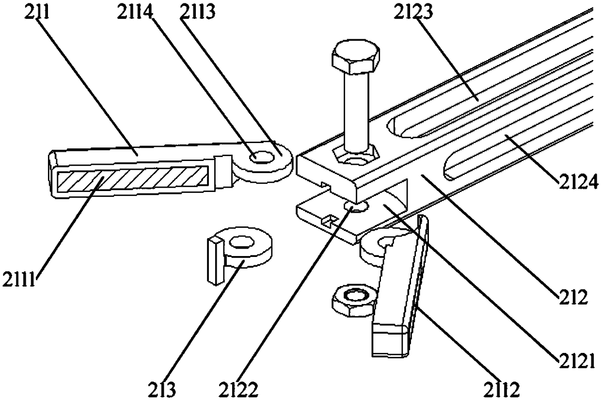
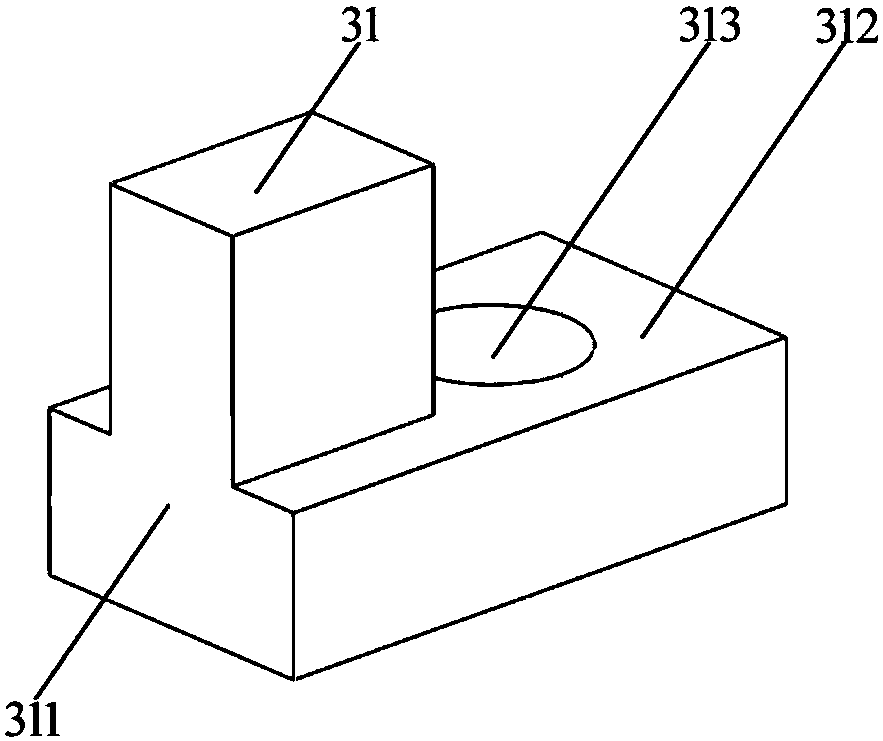
[0027] like Figure 1-4 As shown, a clamping device for thin-walled variable-section pipes includes a base plate 1 on which a first clamping module 2 for clamping variable-section thin-walled pipes and a second clamping module for clamping straight-line thin-walled pipes are installed. Clamping module 3; the first clamping module 2 includes a V-shaped clamping mechanism 21, a vertical slide bar 22 and a U-shaped mounting frame 23; the second clamping module 3 includes several L-shaped clamping sliders ...


PUM


Abstract

The invention discloses a clamping device for a thin-wall variable-section pipe. The clamping device comprises a bottom plate, a first clamping module and a second clamping module, wherein the first clamping module is installed on the bottom plate and used for clamping a variable-section section thin-wall pipe, and the second clamping module is used for clamping a linear section thin-wall pipe; first sliding grooves used for allowing the first clamping module to be installed and second sliding grooves used for allowing the second clamping module to be installed are formed in the bottom plate;the first clamping module comprises V-shaped clamping mechanisms, vertical sliding rods and U-shaped mounting frames, wherein the vertical sliding rods are installed in the first sliding grooves, theU-shaped mounting frames are fixed on the vertical sliding rods, one ends of the V-shaped clamping mechanisms are connected to the vertical sliding rods, the middles of the V-shaped clamping mechanisms are connected to the U-shaped mounting frames, and V-shaped claws of the V-shaped clamping mechanisms are used for clamping the outer periphery of the variable-section section thin-wall pipe; and the second clamping module comprises a plurality of clamping sliding blocks, the clamping sliding blocks are installed in the second sliding grooves and are used for clamping the linear section thin-wall pipe. The clamping device has certain universality, and is accurate in positioning, and high in welding precision and operation efficiency.

Description

technical field [0001] The invention relates to the processing field of thin-wall variable-section pipes, in particular to a clamping device for thin-wall variable-section pipes. Background technique [0002] In the environmental control system, transportation system, and power system in the aerospace field, it is often necessary to use thin-walled variable-section tubes to make full use of the limited space to achieve the overall design and reduce the overall weight. When processing thin-walled variable-section tubes, the straight-line section thin-walled tubes and variable-section thin-walled tubes are generally pretreated by cutting, and then welded. During welding, the positioning requirements for the thin-walled pipes in the straight section and the thin-walled pipes with variable cross-section are very high. Due to the special scope of application of such pipe fittings, which belong to small batch production, if there is no targeted clamping device, the welding operat...

Claims


Application Information

Patent Timeline
Patent Type & Authority Applications(China)
IPC IPC(8): B23K37/053B23K37/04
CPCB23K37/0443B23K37/053B23K37/0533
Inventor 蒋兰芳王亚群邵泓陈志雅马万琪
Owner ZHEJIANG UNIV OF TECH
Learn More