Smart numerically controlled pipeline oil heater

A pipeline oil and heater technology, applied in pipeline heating/cooling, electric heating devices, pipeline systems, etc., can solve the problems of cumbersome maintenance and replacement, and can only monitor fixed-point flow, and achieve high measurement accuracy, good energy-saving effect, and low price Effect

Pending Publication Date: 2018-06-19
西安锐步石油科技有限公司
View PDF0 Cites 1 Cited by
  • Summary
  • Abstract
  • Description
  • Claims
  • Application Information

AI Technical Summary

Problems solved by technology

In the prior art, a pre-set flow meter connected in parallel to the pipeline is generally used, which has the disadvantages of cumbersome maintenance and replacement (generally need to stop oil delivery) and can only monitor fixed-point flow.

Method used


Image

  • Smart numerically controlled pipeline oil heater
  • Smart numerically controlled pipeline oil heater

Examples


Embodiment 1

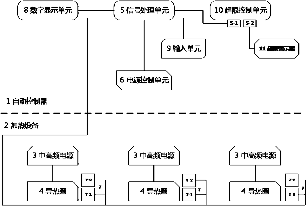
[0051] see figure 1 . The intelligent numerical control pipeline oil heater of this embodiment includes an automatic controller 1 and multiple sets of heating equipment 2 .

[0052]The heating device includes a medium-high frequency power supply 3, a conductive coil 4 and multiple pairs of temperature sensors 7, and the output end of the medium-high frequency power supply 3 is electrically connected to the conductive coil 4;

[0053] The automatic controller 1 includes a signal processing unit 5 and a power control unit 6;

[0054] The paired temperature sensor 7 includes a near-end temperature sensor 7-1 arranged near the conductive coil 4 and a remote temperature sensor 7-2 arranged at a position away from the conductive coil, and the output terminal of the temperature sensor 7 is connected to the The input terminals of the signal processing unit 5 are connected;

[0055] The output end of the signal processing unit 5 is connected to the input end of the power control uni...

Embodiment 2

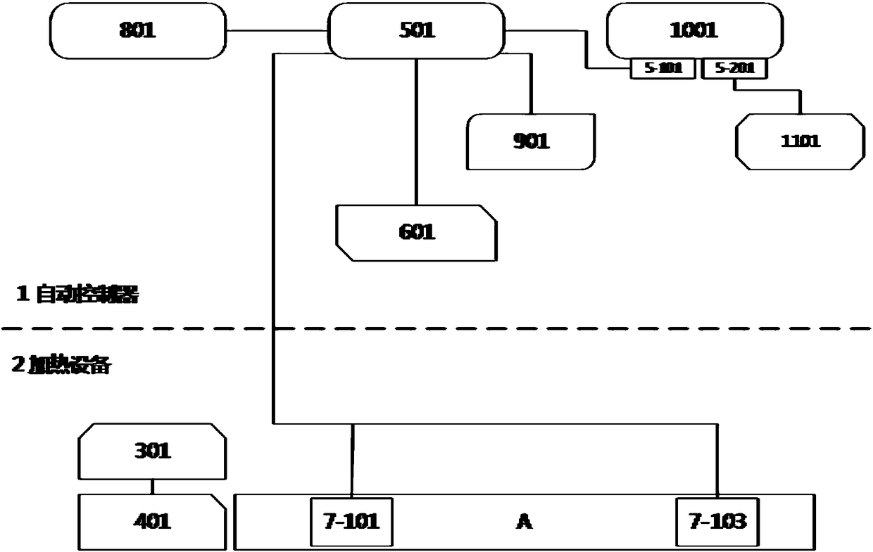
[0057] see figure 2 . When the intelligent numerical control pipeline oil heater performs flow measurement, it shall be implemented as follows.

[0058] The conductive coil 401 is set on the upstream and downstream of the pipeline, and the proximal temperature sensor 7-101 located at the most upstream of the pipeline and the proximal temperature sensor 7-103 located at the most downstream are used as the upstream and downstream temperature sensors. Start the automatic controller 1 to make the conductive coil 401 start heating, and provide a certain amount of heat Q within a specified time.

[0059] The signal processing unit 501 obtains the temperature values ​​of the upstream and downstream temperature sensors 7-101 and 7-103, and calculates the difference ΔT between them F . Input the specific heat capacity c of the measured oil to the automatic controller 1 through the input unit 901, and then the signal processing unit 5 according to the formula Q=c×m×ΔT F Perform cal...


PUM


Abstract

The invention belongs to the field of industrial equipment and particularly relates to a smart numerically controlled pipeline oil heater which comprises an automatic controller and a plurality of sets of heating apparatuses. Each heating apparatus comprises a medium-high frequency power supply, a conductive coil and a plurality of sets of paired temperature sensors, wherein the output end of themedium-high frequency power supply is electrically connected with the conductive coil. The automatic controller comprises a signal processing unit and a power supply control unit. The output ends of the temperature sensors are connected with the input end of the signal processing unit. The output end of the signal processing unit is connected with the input end of the power supply control unit. The output end of the power supply control unit is connected with the medium-high frequency power supply so that the medium-high frequency power supply can be controlled to be started or stopped. The smart numerically controlled pipeline oil heater can achieve non-invasive pipeline heating and flow measurement independently or simultaneously, and has the advantages of low energy consumption, high adaptability and reliable performance.

Description

technical field [0001] The invention belongs to the field of industrial equipment, and in particular relates to an intelligent numerical control pipeline oil heater. Background technique [0002] The crude oil produced at the wellhead has a high viscosity, and it is easy to freeze and block the oil pipeline when the temperature is low in winter. stand. [0003] The heating methods disclosed in the prior art include steam tracing and water bath heating. In the above-mentioned method, gas-fired, oil-fired boilers and electric water jacket boilers are the main devices for generating heat energy. Since the above-mentioned device generally includes many auxiliary equipment such as a circuit, a heat medium circuit, and a heat exchanger circuit, the system is complex and huge, with large thermal inertia and thermal hysteresis; and the above-mentioned method belongs to open-loop heating, not for controlling the export of crude oil. Temperature is the control object, so the therma...

Claims


Application Information

Patent Timeline
IPC IPC(8): F16L53/38F17D3/18F17D5/00H05B1/02
CPCH05B1/023F17D3/18F17D5/00
Inventor 陈永宏
Owner 西安锐步石油科技有限公司
Why Eureka
Try Eureka