Part punching device

A technology for punching devices and parts, which is applied in the directions of feeding devices, positioning devices, storage devices, etc., can solve the problems of small application range of punching machines and no fixed parts of punching machines, so as to increase the application range and increase contact Area, the effect of holding the workpiece firmly

Inactive Publication Date: 2018-06-19
重庆市璧山区合成机械制造有限公司
View PDF5 Cites 8 Cited by
  • Summary
  • Abstract
  • Description
  • Claims
  • Application Information

AI Technical Summary

Problems solved by technology

[0004] The present invention intends to provide a part punching device to solve the problem that the existing punching machine has no mechanism for fixing parts or has a fixing mechanism but the application range of the punching machine is small

Method used


Image

  • Part punching device
  • Part punching device
  • Part punching device

Examples


Embodiment Construction

[0022] Further detailed explanation through specific implementation mode below:

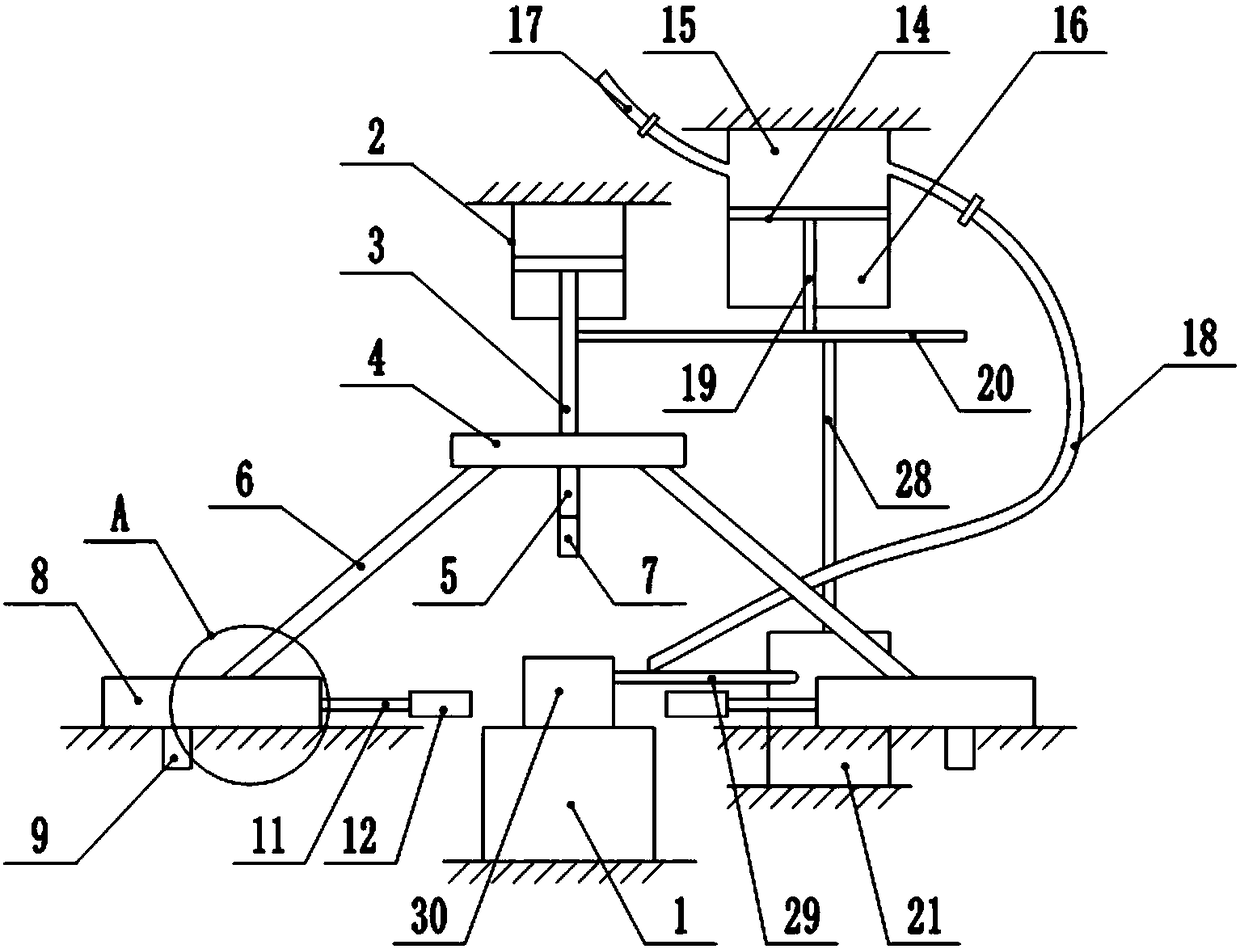
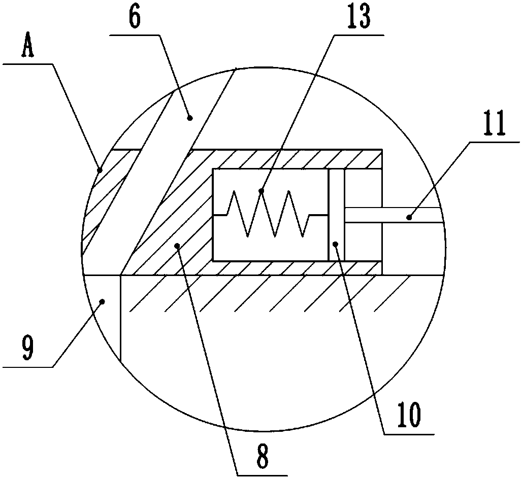
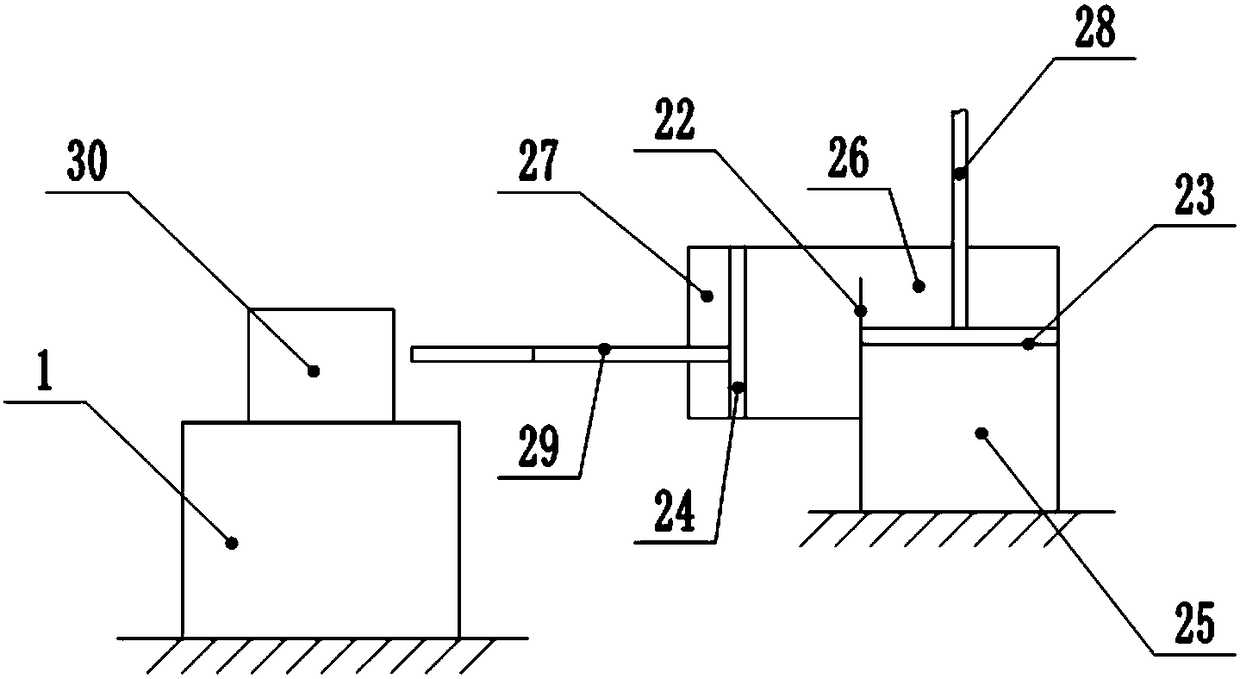
[0023] The reference signs in the drawings of the description include: stamping table 1, telescopic cylinder 2, first piston rod 3, horizontal plate 4, vertical rod 5, inclined rod 6, punching cutter head 7, slider 8, stopper 9, Sliding plate 10, cross bar 11, clamping sheet 12, spring 13, second piston 14, upper chamber 15, lower chamber 16, air intake pipe 17, air outlet pipe 18, second piston rod 19, connecting rod 20, second Cylinder 21, partition 22, third piston 23, fourth piston 24, first chamber 25, second chamber 26, third chamber 27, third piston rod 28, fourth piston rod 29, workpiece 30 .

[0024] This embodiment is basically as figure 1 As shown, a part punching device includes a frame and a stamping table 1 for placing a workpiece 30. The frame is fixedly equipped with a telescopic cylinder 2, and the telescopic cylinder 2 is slidably connected with a first piston, and the first p...


PUM


Abstract

The invention relates to the technical field of machining, and specifically discloses a part punching device. The part punching device comprises a rack and a punching platform, wherein the punching platform is used for bearing a workpiece; the rack is fixedly provided with a telescopic air cylinder; the telescopic air cylinder is internally connected with a first piston in a sliding way; the firstpiston is fixedly connected with a first piston rod; the first piston rod is fixedly connected with a transverse plate; the transverse plate is fixedly connected with a vertical rod and two oblique rods; a vertical central line of the vertical rod is coincided with a vertical central line of the transverse plate; the vertical rod is in threaded connection with a punching tool bit; the two obliquerods are symmetrically arranged along the vertical central line of the transverse plate; each oblique rod is sleeved with a sliding block; the sliding blocks are connected to the rack in the slidingway; grooves are formed in the sliding blocks; the grooves are internally connected with sliding plates in the sliding way; one side of each sliding plate is fixedly connected with a transverse rod, and a spring is fixedly connected between the other side of the sliding plate and the bottom wall of the corresponding groove; the transverse rods are in threaded connection with clamping pieces for clamping the workpiece. The part punching device disclosed by the invention is capable of realizing the punching on parts in different sizes, and an application range of the part punching device is increased.

Description

technical field [0001] The invention relates to the technical field of machining, and specifically discloses a part punching device. Background technique [0002] Punching refers to the method of separating the material in the blank from the blank with a closed outline to obtain a punching part with holes. It can punch various patterns of holes on steel plates, leather, cloth, wood and other materials to adapt to different shapes. Specifically, there are cross holes, fish scale holes, figure-eight holes, hexagonal holes, round holes and triangular holes and so on. [0003] At present, the method of punching holes on parts is basically to use a punching machine to punch holes, which has high efficiency and high punching quality. However, the existing punching machines need to manually place the parts on the punching platform, and some punching machines do not have a mechanism to fix the parts, and can only rely on manual hand-held parts to fix the position of the parts to pr...

Claims


Application Information

Patent Timeline
IPC IPC(8): B21D28/24B21D43/00B26F1/02B26D7/02B27M1/04
CPCB21D28/24B21D43/003B26D7/02B26F1/02B27M1/04
Inventor 陈世刚
Owner 重庆市璧山区合成机械制造有限公司
Why Eureka
Try Eureka