Double-stator fixed piezoelectric inertial driver and its driving method
A driving method and fixed technology, applied in the direction of piezoelectric effect/electrostrictive or magnetostrictive motors, generators/motors, electrical components, etc., can solve the problems of small load output, poor motion stability, complex structure, etc. , to achieve the effect of reducing the displacement return rate, strong load capacity and increasing friction driving force
- Summary
- Abstract
- Description
- Claims
- Application Information
AI Technical Summary
Problems solved by technology
Method used
Image
Examples
specific Embodiment approach 1
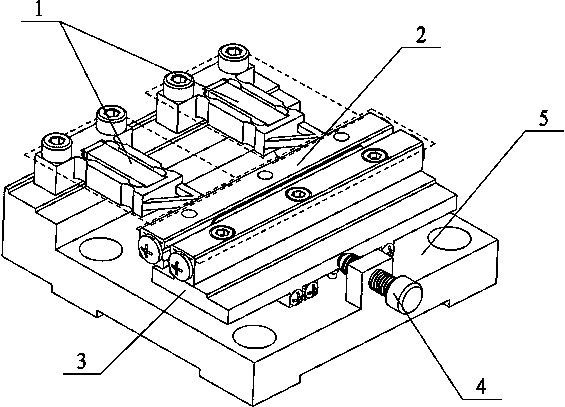
[0030] Specific implementation mode one: combine Figure 1~Figure 11 Describe this embodiment, this embodiment provides a specific implementation of a double-stator fixed piezoelectric inertia driver, the specific implementation of a double-stator fixed piezoelectric inertia driver is expressed as follows:
[0031] The dual-stator fixed piezoelectric inertial driver is composed of a cable-stayed stator assembly 1 , a mover assembly 2 , a sliding boss 3 , a micro-displacement adjustment device 4 and a base 5 .
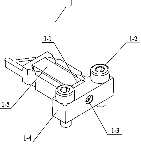
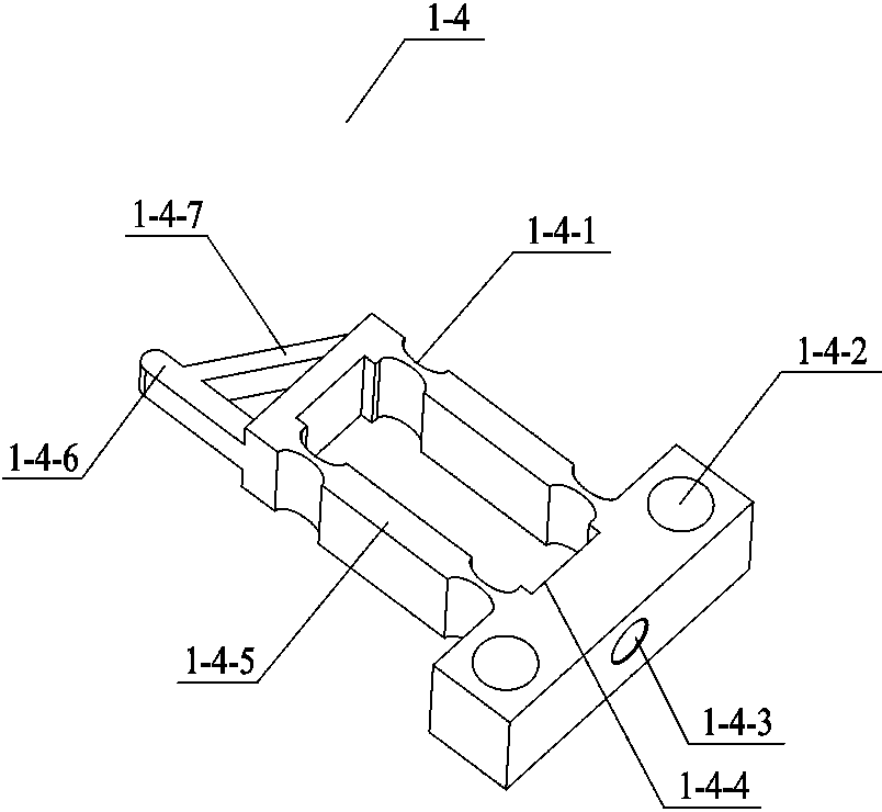
[0032] The cable-stayed stator assembly 1 includes a square gasket 1-1, a hinge fixing bolt 1-2, a kimmie screw 1-3, a rectangular structural hinge 1-4 and a piezoelectric stack 1-5. The square washer 1-1 and Kimi screw 1-3 fix the piezoelectric stack 1-5 in the rectangular structural hinge 1-4. The piezoelectric stacks 1-5 can be products from PI or NEC. The square gasket 1-1 is made of tungsten steel, the purpose is to protect the piezoelectric stack 1-5 and prevent...
specific Embodiment approach 2
[0037] Specific implementation mode two: combination Figure 11-12 To illustrate this embodiment, this embodiment proposes a specific implementation of a double-stator fixed piezoelectric inertia driver driving method, and the double-stator fixed piezoelectric inertia driver driving method is expressed as follows:
[0038] The driving method of the double-stator fixed piezoelectric inertia driver can be divided into output enhancement type and motion emergency stop type. The main reason is that the double-stator fixed piezoelectric inertia driver adopts a cable-pull motion converter 1-4-7 structure, so that The uneven distribution of the axial stiffness of the cable-stayed stator assembly 1 produces lateral displacement. Adjust the positive contact pressure between the cable-stayed stator assembly 1 and the mover assembly 2, and then adjust the cable-stayed stator assembly 1 and the mover assembly. 2; at the same time, under the excitation of different combinations of asymmetr...
specific Embodiment approach 3
[0062] Specific implementation mode three: combination Figure 12 , 13, 14 illustrate this embodiment, this embodiment proposes a specific implementation of a cable-stayed stator assembly 1 back-to-back installed dual-stator fixed cable-stayed piezoelectric inertia driver driving method, the cable-stayed The driving method of the double-stator fixed piezoelectric inertial driver with stator assemblies installed back-to-back is expressed as follows:
[0063] Cable-pull stator assembly 1. The driving method of the double-stator fixed piezoelectric inertia driver installed back to back can be divided into output enhancement type and motion emergency stop type, mainly the double-stator fixed piezoelectric inertia driver installed back-to-back. The inertial driver adopts a cable-stayed motion converter 1-4-7 structure, which makes the axial stiffness distribution of the cable-stayed stator assembly 1 uneven and produces lateral displacement. Adjust the distance between the cable-s...
PUM
 Abstract
Description
Claims
Application Information
 - R&D
- Intellectual Property
- Life Sciences
- Materials
- Tech Scout
- Unparalleled Data Quality
- Higher Quality Content
- 60% Fewer Hallucinations
Browse by: Latest US Patents, China's latest patents, Technical Efficacy Thesaurus, Application Domain, Technology Topic, Popular Technical Reports.
© 2025 PatSnap. All rights reserved.Legal|Privacy policy|Modern Slavery Act Transparency Statement|Sitemap|About US| Contact US: help@patsnap.com


