
Low-voltage compensation device and method of energy-saving power distribution network

A compensation device and low-voltage technology, applied in circuit devices, AC network voltage adjustment, photovoltaic power generation, etc., can solve problems such as low-voltage compensation in distribution networks and low voltage at public connection points, and avoid loss and nonlinear problems. The effect of large application prospects

Active Publication Date: 2018-06-15
西安翌飞核能装备股份有限公司
View PDF5 Cites 4 Cited by
  • Summary
  • Abstract
  • Description
  • Claims
  • Application Information

AI Technical Summary

Problems solved by technology

[0004] The purpose of the present invention is to solve the low-voltage compensation problem of distribution network, and propose a new low-voltage compensation device and method for energy-saving distribution network, which can significantly improve efficiency, reduce volume and weight, and can solve the problem of multiple low-voltage compensation equipment at the same time. Simultaneous access to the problem of low voltage at the common connection point

Method used

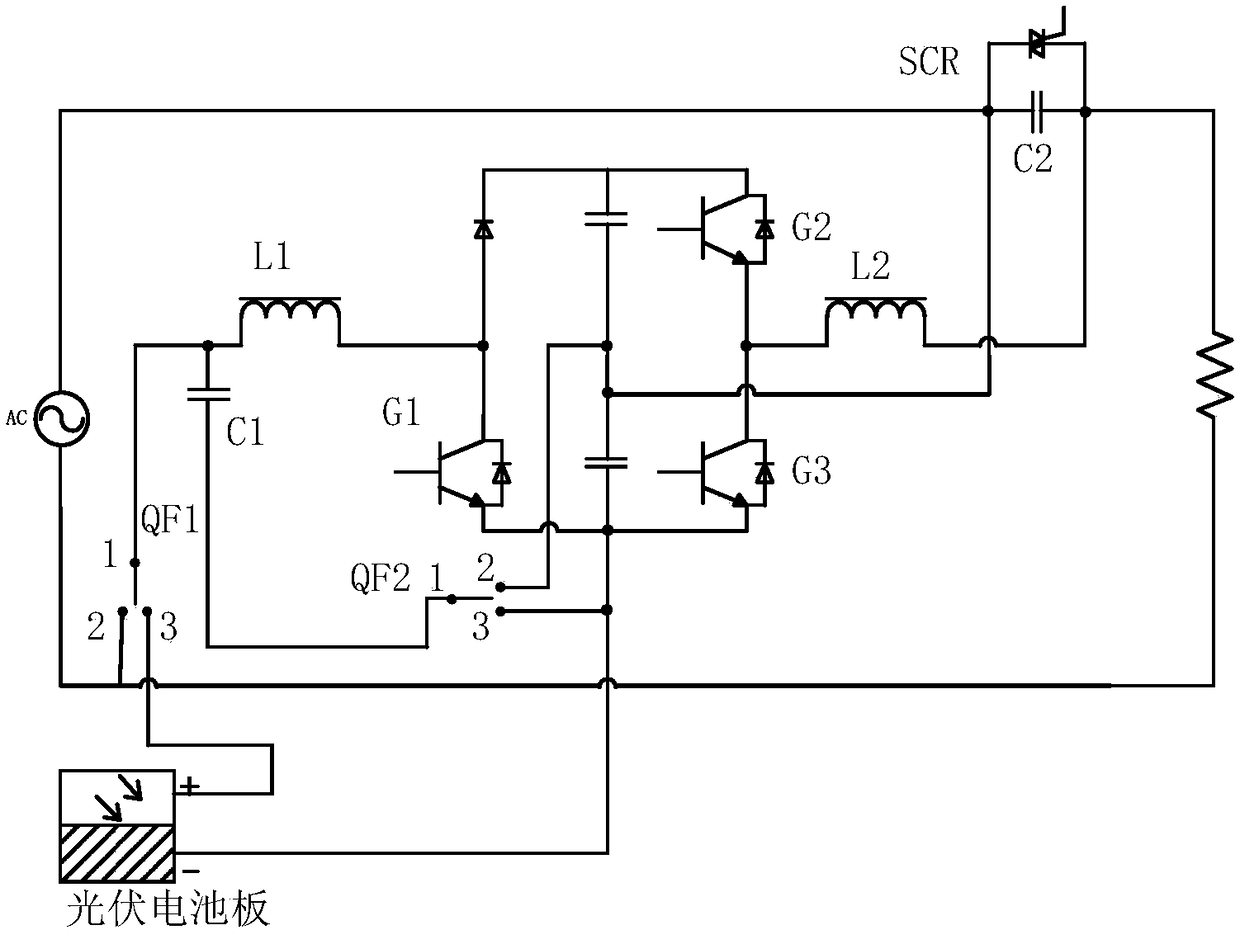
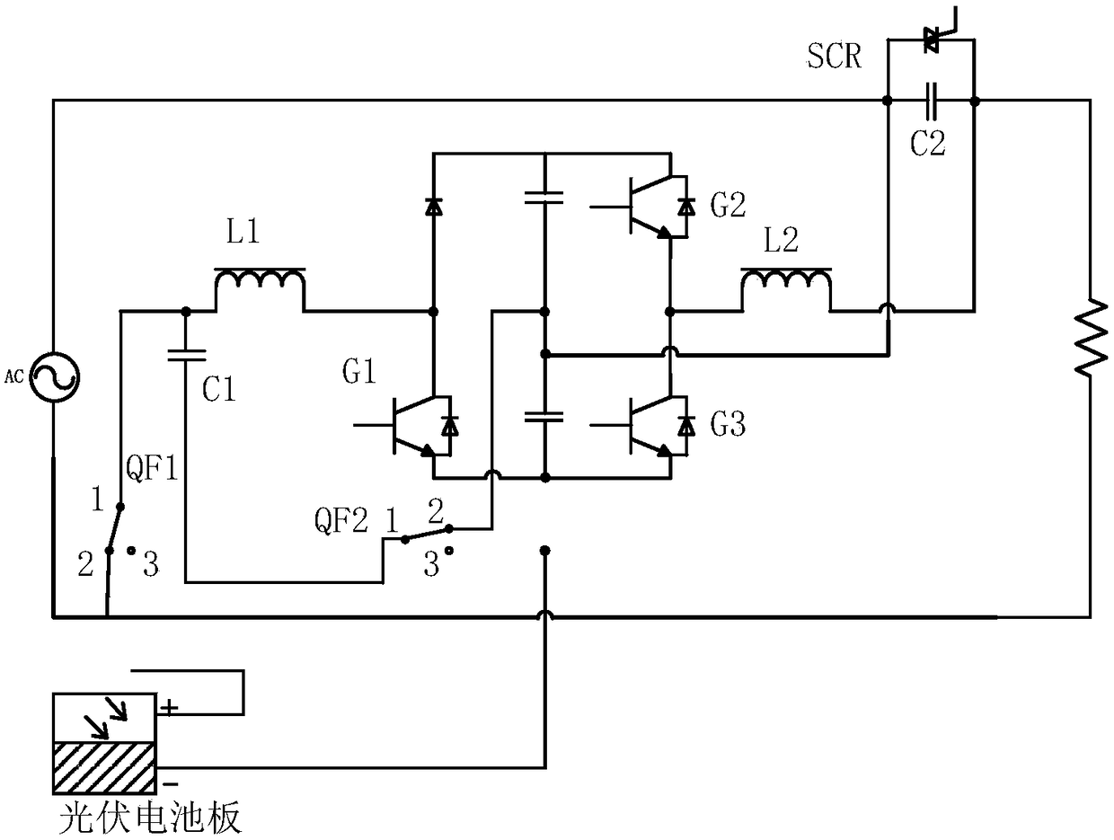
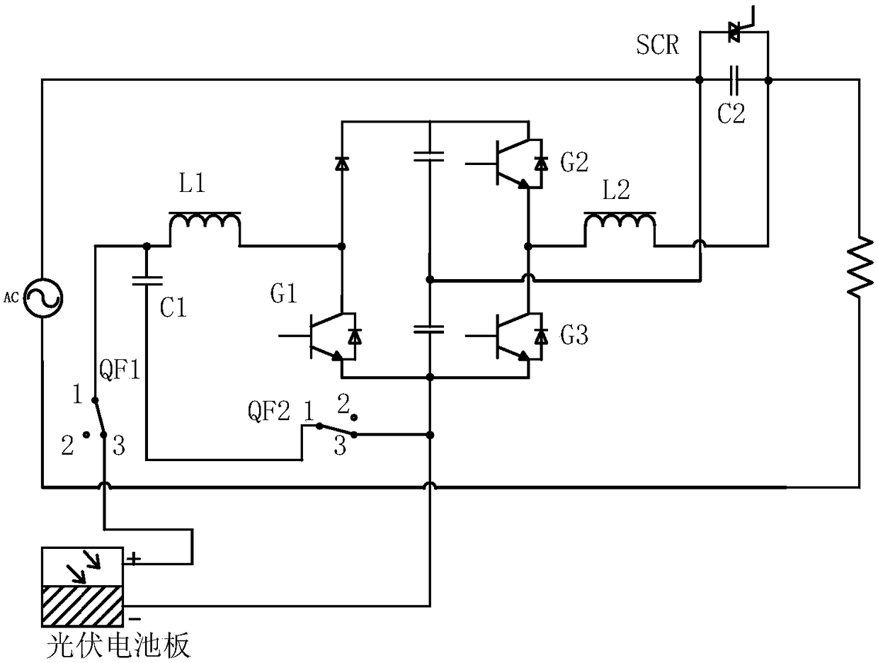

Image

  • Low-voltage compensation device and method of energy-saving power distribution network
  • Low-voltage compensation device and method of energy-saving power distribution network
  • Low-voltage compensation device and method of energy-saving power distribution network

Examples


Embodiment Construction

[0036] Below in conjunction with specific embodiment and accompanying drawing, the present invention is described in further detail:

[0037] Such as figure 1 As shown, the equipment topology is divided into rectification part, inverter part and bypass unit. The rectification part includes: relay QF1, filter capacitor C1, AC reactance L1, IGBT tube G1, rectifier diode, photovoltaic panel. The inverter part includes: relay QF2, upper and lower IGBT tubes G2 and G3, inverter inductor L2, and filter capacitor C2. The bypass unit includes: bidirectional thyristor SCR.

[0038] The implementation steps of the energy-saving distribution network low-voltage compensation device are as follows:

[0039] Grid connection mode:

[0040] a. SCR is turned on, and the load is energized.

[0041] b. QF1 closes to 2 position, QF2 closes to 2 position.

[0042] The rectification part G1 blocks the pulse, the inverter part does not start (blocks the pulses of G2 and G3), and rectifies thro...


PUM


Abstract

The invention discloses a low-voltage compensation device and method of an energy-saving power distribution network. The device is divided into a rectification part, an inversion part and a bypass unit, wherein the rectification part comprises a relay QF1, a filtering capacitor C1, an AC reactor L1, an IGBT tube G1, a rectification diode and a photovoltaic cell panel, the inversion part comprisesa relay QF2, an IGBT tube G2, an IGBT tube G3, an inversion inductor L2 and a filtering capacitor C2, and the bypass unit comprises a bidirectional thyristor SCR. With the adoption of a series voltagecompensation mode, the problem of low voltage of the power distribution network is solved, and the device only needs to provide a part of load power; with the adoption of a transformerless DC seriesmode, the problems of loss and non-linearity of the transformer are prevented; combined with photovoltaic power generation, a working mode is switched, and the problem of extremely low voltage of a plurality of voltage regulation devices simultaneously running at access points is solved; and meanwhile, photovoltaic power generation is fully utilized, the effect of energy saving and emission reduction is achieved.

Description

technical field [0001] The invention belongs to the field of power electronic control, and relates to an energy-saving distribution network low-voltage compensation device and method. Background technique [0002] With the continuous development of the economy, the load of the distribution network has undergone tremendous changes. At the same time, with the use of new household appliances and new load equipment, many distribution networks have experienced heavy load problems. Due to the voltage drop caused by cables, the incoming line voltage of many users is lower than 220V, or even lower than 160V. For example, with the influence of the greenhouse effect, the weather in summer is getting hotter and hotter, and many users connect to air conditioners. However, in the hottest time of summer, a large number of air conditioners are connected, resulting in heavy loads and excessive incoming line voltage. Low, the air conditioner can't run at full power, or even won't run. Tran...

Claims


Application Information

Patent Timeline
Patent Type & Authority Applications(China)
IPC IPC(8): H02J3/12H02J3/38
CPCH02J3/383H02J3/12Y02E10/56
Inventor 李翔
Owner 西安翌飞核能装备股份有限公司
Learn More