
An electronic control development and test system for simulating fuel cells

A fuel cell and test system technology, applied in electrical testing/monitoring, measuring electricity, measuring devices, etc., to achieve the effect of safely developing battery systems and improving reliability and stability

Active Publication Date: 2019-12-06
DALIAN INST OF CHEM PHYSICS CHINESE ACAD OF SCI
View PDF7 Cites 0 Cited by
  • Summary
  • Abstract
  • Description
  • Claims
  • Application Information

AI Technical Summary

Problems solved by technology

These are things that cannot be accomplished by pure virtual devices that can only simulate simple or single faults and operating states

Method used


Image

  • An electronic control development and test system for simulating fuel cells
  • An electronic control development and test system for simulating fuel cells
  • An electronic control development and test system for simulating fuel cells

Examples


Embodiment Construction

[0031] The present invention will be further described in detail below in conjunction with the accompanying drawings and embodiments.

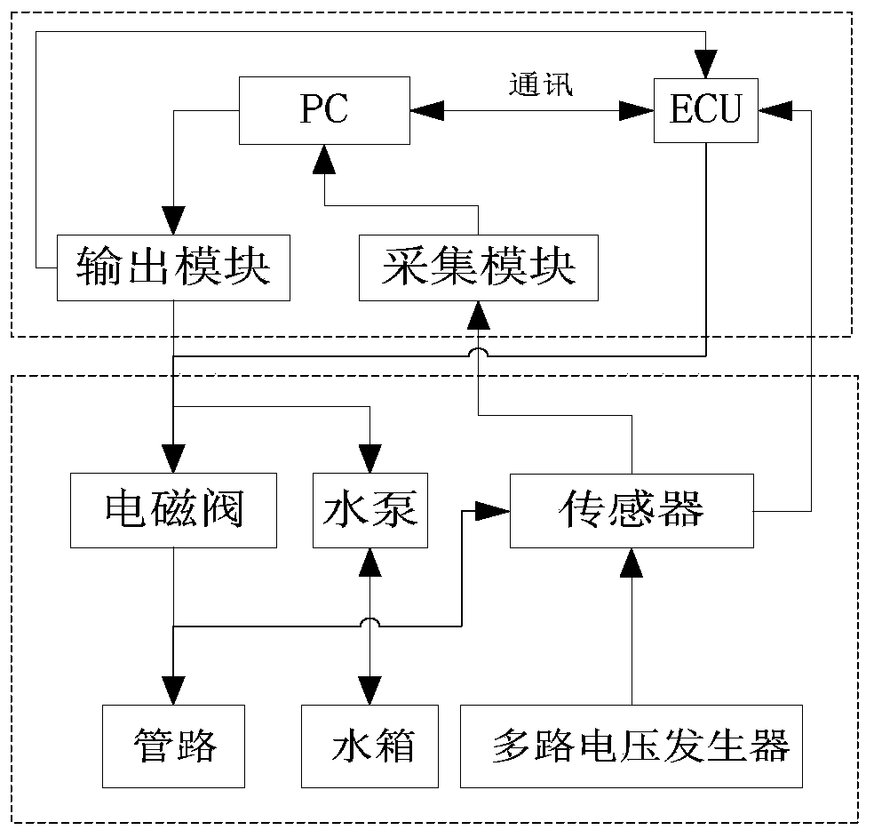
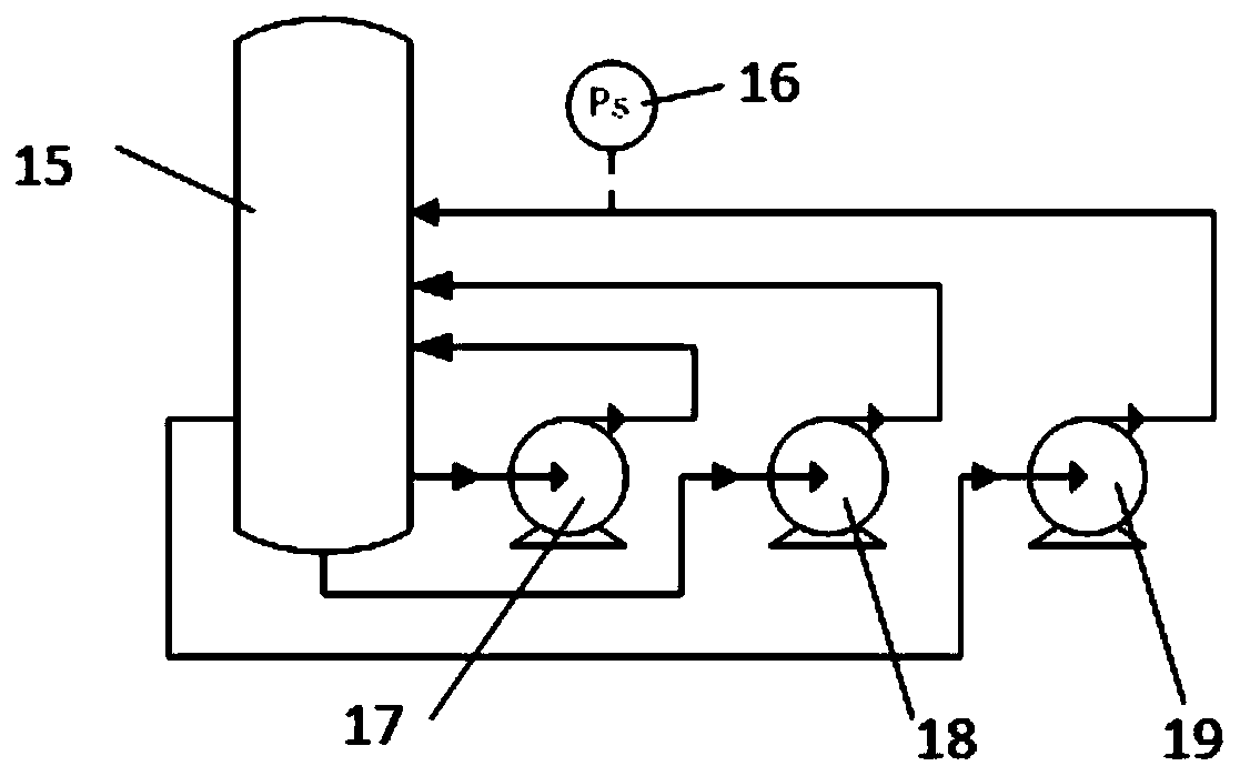
[0032] The mechanical pipeline of the test bench is completely the actual working pipeline of a fuel cell system. The difference is that a buffer tank is used to simulate the cavity volume of the battery. In terms of gas source, the air source or nitrogen source is uniformly used to simulate hydrogen, oxygen, and nitrogen sources after decompression and stabilization. The three pressure regulator valves can adjust the air source to simulate the real air source pressure. After the ECU is connected to the pipeline pressure control solenoid valve, the test pressure balance program can be developed. After debugging, there will be deviations when transplanted to the real system, but the deviations will not be very large, and a slight adjustment is enough. Install a multi-channel voltage generator to simulate the output voltage of the battery. The...


PUM


Abstract

The invention relates to an electronically controlled development and testing system for simulating fuel cells, comprising: a hydrogen passage, an oxygen passage, and a heat dissipation water passage; one end of an acquisition module is connected to a sensor of the hydrogen passage, an oxygen passage, and a heat dissipation water passage, and the other end is connected to a PC to collect the hydrogen passage, The status information of the oxygen channel and the cooling water channel is fed back to the PC; the output module is connected to the PC to receive the control command from the PC, and the other end is connected to the hydrogen channel, the oxygen channel and the cooling water channel to control the status of the hydrogen channel, the oxygen channel and the cooling water channel; ECU Connect the output terminal of the output module to receive the output command from the PC; the other end is connected to the sensors of the hydrogen passage, oxygen passage and heat dissipation water passage, collect the status information of the hydrogen passage, oxygen passage and heat dissipation water passage, and control them; the PC communicates through the serial port Connect with ECU for data monitoring. The invention contributes to rapid and safe development of battery systems and improves module reliability and stability.

Description

technical field [0001] The invention relates to a fuel cell system integration technology, in particular to an electric control development and testing system simulating a fuel cell. Background technique [0002] The electronic control subsystem of the fuel cell system consists of three layers of control components. The first layer is the control core ECU, that is, the electronic control unit. As the control core of the whole module, it plays the functions of collecting data, controlling various electronic components in the module, and sending data. The second layer is data collection, including various inspection, temperature, pressure, flow, insulation, current, and voltage sensors. The system collects signals through these sensors and sends them to the ECU for processing. Through these data analysis, the system can judge the working status of the battery system and make corresponding feedback, thus forming a closed control loop. The third layer is the executive compon...

Claims


Application Information

Patent Timeline
Patent Type & Authority Patents(China)
IPC IPC(8): G01R31/385G05B23/02
CPCG01R31/385G05B23/02
Inventor 林永俐周利邵志刚
Owner DALIAN INST OF CHEM PHYSICS CHINESE ACAD OF SCI
Learn More